


1-17
Cisco ME 3400 Ethernet Access Switch Software Configuration Guide
OL-9639-06
Chapter 1 Overview
Where to Go Next
• Provider routers or core routers are any routers in the service provider network that do not attach to
CE devices.
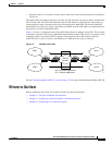
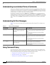
With multi-VRF CE, multiple customers can share one CE, and only one physical link is used between
the CE and the PE. The shared CE maintains separate VRF tables for each customer and switches or
routes packets for each customer based on its own routing table. Multi-VRF CE extends limited PE
functionality to a CE device, giving it the ability to maintain separate VRF tables to extend the privacy
and security of a VPN to the branch office.
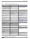
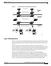
Figure 1-3 shows a configuration using Cisco ME 3400 switches as multiple virtual CEs. This scenario
is suited for customers who have low bandwidth requirements for their VPN service, for example, small
companies. In this case, multi-VRF CE support is required in the Cisco ME switches. Because
multi-VRF CE is a Layer 3 feature, each interface in a VRF must be a Layer 3 interface.
Figure 1-3 Multiple Virtual CEs
See the “Configuring Multi-VRF CE” section on page 35-74 for more information about Multi-VRF-CE.
Where to Go Next
Before configuring the switch, review these sections for startup information:
• Chapter 2, “Using the Command-Line Interface”
• Chapter 3, “Assigning the Switch IP Address and Default Gateway”
• Chapter 4, “Configuring Cisco IOS CNS Agents”
VPN 1
VPN 2
VPN 1
VPN 2
CE2PE1 PE2
Service
provider
CE1
CE = Customer-edge device
PE = Provider-edge device
101385