


15-15
Cisco ME 3400 Ethernet Access Switch Software Configuration Guide
OL-9639-06
Chapter 15 Configuring MSTP
Configuring MSTP Features
For information about the supported number of spanning-tree instances, see the “Supported
Spanning-Tree Instances” section on page 14-10.
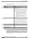
MSTP Configuration Guidelines
These are the configuration guidelines for MSTP:
• On the Cisco ME switch, MSTP is supported only on NNIs or ENIs on which STP has been enabled.
You enable STP on an ENI by entering the spanning-tree interface configuration command. UNIs
do not participate in MSTP.
• When you enable MST by using the spanning-tree mode mst global configuration command, RSTP
is automatically enabled.
• For two or more switches to be in the same MST region, they must have the same VLAN-to-instance
map, the same configuration revision number, and the same name.
• The switch supports up to 65 MST instances. The number of VLANs that can be mapped to a
particular MST instance is unlimited.
• PVST+, rapid PVST+, and MSTP are supported, but only one version can be active at any time. (For
example, all VLANs run PVST+, all VLANs run rapid PVST+, or all VLANs run MSTP.) For more
information, see the
“Spanning-Tree Interoperability and Backward Compatibility” section on
page 14-10. For information on the recommended trunk port configuration, see the “Interaction with
Other Features” section on page 11-16.
• You can manually configure the MST configuration (region name, revision number, and
VLAN-to-instance mapping) on each switch within the MST region by using the command-line
interface (CLI) or through the SNMP support.
• For load balancing across redundant paths in the network to work, all VLAN-to-instance mapping
assignments must match; otherwise, all traffic flows on a single link.
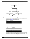
• All MST boundary ports must be forwarding for load balancing between a PVST+ and an MST
cloud or between a rapid-PVST+ and an MST cloud. For this to occur, the IST master of the MST
cloud should also be the root of the CST. If the MST cloud consists of multiple MST regions, one
of the MST regions must contain the CST root, and all of the other MST regions must have a better
path to the root contained within the MST cloud than a path through the PVST+ or rapid-PVST+
cloud. You might have to manually configure the switches in the clouds.
• Partitioning the network into a large number of regions is not recommended. However, if this
situation is unavoidable, we recommend that you partition the switched LAN into smaller LANs
interconnected by routers or non-Layer 2 devices.
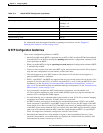
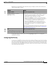
Spanning-tree port cost (configurable on a per-CIST port basis) 1000 Mbps: 4.
100 Mbps: 19.
10 Mbps: 100.
Hello time 2 seconds.
Forward-delay time 15 seconds.
Maximum-aging time 20 seconds.
Maximum hop count 20 hops.
Table 15-4 Default MSTP Configuration (continued)
Feature Default Setting