


13-2
Cisco ME 3400 Ethernet Access Switch Software Configuration Guide
OL-9639-06
Chapter 13 Configuring IEEE 802.1Q and Layer 2 Protocol Tunneling
Understanding IEEE 802.1Q Tunneling
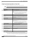
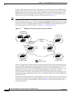
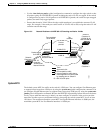
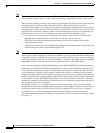
Customer traffic tagged in the normal way with appropriate VLAN IDs comes from an IEEE 802.1Q
trunk port on the customer device and into a tunnel port on the service-provider edge switch. The link
between the customer device and the edge switch is asymmetric because one end is configured as an
IEEE 802.1Q trunk port, and the other end is configured as a tunnel port. You assign the tunnel port
interface to an access VLAN ID that is unique to each customer. See
Figure 13-1.
Note By default, VLANs configured on the switch are user network interface-enhanced network interface
(UNI-ENI) isolated VLANs. In a UNI-ENI isolated VLAN, IEEE 802.1Q tunneled access ports on the
switch are isolated from each other. If you use the uni-vlan community VLAN configuration command
to change a VLAN to a UNI-ENI community VLAN, local switching occurs between these ports. For
more information about UNI-ENI VLANs, see Chapter 11, “Configuring VLANs.”
Figure 13-1 IEEE 802.1Q Tunnel Ports in a Service-Provider Network
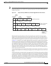
Packets coming from the customer trunk port into the tunnel port on the service-provider edge switch
are normally IEEE 802.1Q-tagged with the appropriate VLAN ID. The the tagged packets remain intact
inside the switch and when they exit the trunk port into the service-provider network, they are
encapsulated with another layer of an IEEE 802.1Q tag (called the metro tag) that contains the VLAN
ID that is unique to the customer. The original customer IEEE 802.1Q tag is preserved in the
encapsulated packet. Therefore, packets entering the service-provider network are double-tagged, with
the outer (metro) tag containing the customer’s access VLAN ID, and the inner VLAN ID being that of
the incoming traffic.
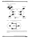
When the double-tagged packet enters another trunk port in a service-provider core switch, the outer tag
is stripped as the switch processes the packet. When the packet exits another trunk port on the same core
switch, the same metro tag is again added to the packet.
Figure 13-2 shows the tag structures of the
double-tagged packets.
Customer A
VLANs 1 to 100
Customer B
VLANs 1 to 200
Customer B
VLANs 1 to 200
Customer A
VLANs 1 to 100
Tunnel port
VLAN 40
Tunnel port
VLAN 30
Trunk
ports
Trunk
ports
Tunnel port
VLAN 30
Tunnel port
VLAN 40
Service
provider
74016
Trunk
Asymmetric link
Tunnel port
VLAN 30