


14-8
Cisco ME 3400 Ethernet Access Switch Software Configuration Guide
OL-9639-06
Chapter 14 Configuring STP
Understanding Spanning-Tree Features
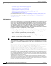
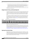
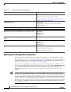
Figure 14-2 Spanning-Tree Topology
When the spanning-tree topology is calculated based on default parameters, the path between source and
destination end stations in a switched network might not be ideal. For instance, connecting higher-speed
links to an interface that has a higher number than the root port can cause a root-port change. The goal
is to make the fastest link the root port.
For example, assume that one port on Switch B is a Gigabit Ethernet link and that another port on
Switch
B (a 10/100 link) is the root port. Network traffic might be more efficient over the Gigabit
Ethernet link. By changing the spanning-tree port priority on the Gigabit Ethernet port to a higher
priority (lower numerical value) than the root port, the Gigabit Ethernet port becomes the new root port.
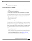
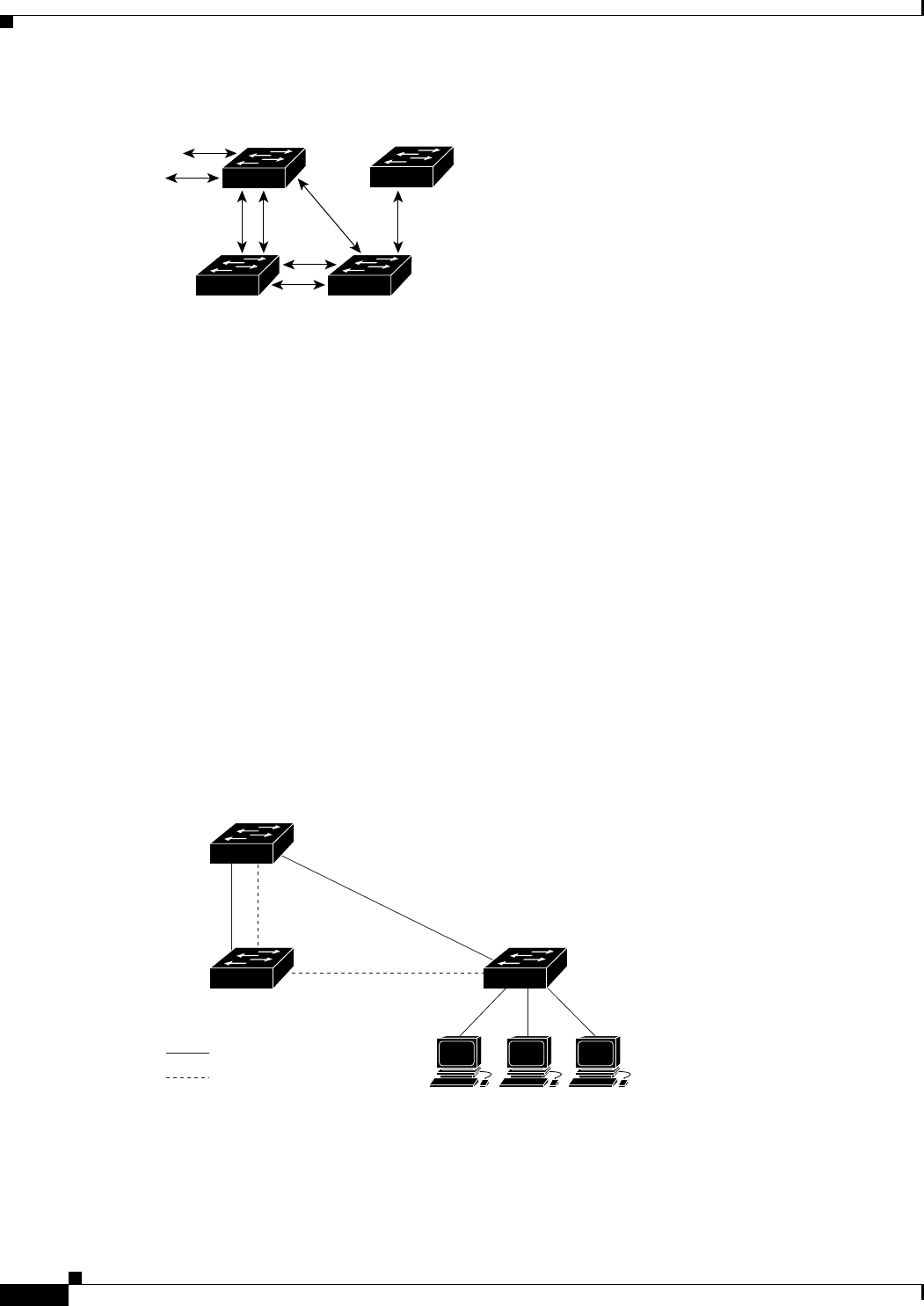
Spanning Tree and Redundant Connectivity
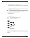
You can create a redundant backbone with spanning tree by connecting two switch interfaces that are
participating in spanning tree to another device or to two different devices, as shown in
Figure 14-3.
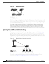
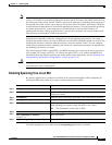
Spanning tree automatically disables one interface but enables it if the other one fails. If one link is
high-speed and the other is low-speed, the low-speed link is always disabled. If the speeds are the same,
the port priority and port ID are added together, and spanning tree disables the link with the lowest value.
Figure 14-3 Spanning Tree and Redundant Connectivity
You can also create redundant links between switches by using EtherChannel groups. For more
information, see
Chapter 34, “Configuring EtherChannels and Link-State Tracking.”
86475
DP
DP
RP
DP
RP
DP
RP = Root Port
DP = Designated Port
DP
RP
DA
CB
101226
Workstations
Active link
Blocked link