


15-4
Cisco ME 3400 Ethernet Access Switch Software Configuration Guide
OL-9639-06
Chapter 15 Configuring MSTP
Understanding MSTP
For correct operation, all switches in the MST region must agree on the same IST master. Therefore, any
two switches in the region synchronize their port roles for an MST instance only if they converge to a
common IST master.
Operations Between MST Regions
If there are multiple regions or legacy IEEE 802.1D switches within the network, MSTP establishes and
maintains the CST, which includes all MST regions and all legacy STP switches in the network. The
MST instances combine with the IST at the boundary of the region to become the CST.
The IST connects all the MSTP switches in the region and appears as a subtree in the CST that
encompasses the entire switched domain, with the root of the subtree being the IST master. The MST
region appears as a virtual switch to adjacent STP switches and MST regions.
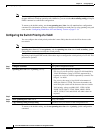
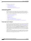
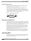
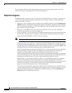
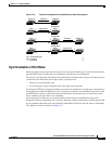
Figure 15-1 shows a network with three MST regions and a legacy IEEE 802.1D switch (D). The IST
master for region 1 (A) is also the CST root. The IST master for region 2 (B) and the IST master for
region 3 (C) are the roots for their respective subtrees within the CST. The RSTP runs in all regions.
Figure 15-1 MST Regions, IST Masters, and the CST Root
Figure 15-1 does not show additional MST instances for each region. Note that the topology of MST
instances can be different from that of the IST for the same region.
Only the CST instance sends and receives BPDUs, and MST instances add their spanning-tree
information into the BPDUs to interact with neighboring switches and compute the final spanning-tree
topology. Because of this, the spanning-tree parameters related to BPDU transmission (for example,
IST master
and CST root
IST master IST master
A
MST Region 1
D
Legacy 802.1D
B
MST Region 2 MST Region 3
C
88762