


35-76
Cisco ME 3400 Ethernet Access Switch Software Configuration Guide
OL-9639-06
Chapter 35 Configuring IP Unicast Routing
Configuring Multi-VRF CE
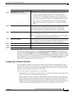
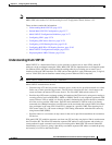
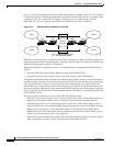
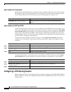
Figure 35-6 shows a configuration using Cisco ME 3400 switches as multiple virtual CEs. This scenario
is suited for customers who have low bandwidth requirements for their VPN service, for example, small
companies. In this case, multi-VRF CE support is required in the Cisco ME switches. Because
multi-VRF CE is a Layer 3 feature, each interface in a VRF must be a Layer 3 interface.
Figure 35-6 Switches Acting as Multiple Virtual CEs
When the CE switch receives a command to add a Layer 3 interface to a VRF, it sets up the appropriate
mapping between the VLAN ID and the policy label (PL) in multi-VRF-CE-related data structures and
adds the VLAN ID and PL to the VLAN database.
When multi-VRF CE is configured, the Layer 3 forwarding table is conceptually partitioned into two
sections:
• The multi-VRF CE routing section contains the routes from different VPNs.
• The global routing section contains routes to non-VPN networks, such as the Internet.
VLAN IDs from different VRFs are mapped into different policy labels, which are used to distinguish
the VRFs during processing. If no route is found in the multi-VRF CE section of the Layer 3 forwarding
table, the global routing section is used to determine the forwarding path. For each new VPN route
learned, the Layer 3 setup function retrieves the policy label by using the VLAN ID of the ingress port
and inserts the policy label and new route to the multi-VRF CE routing section. If the packet is received
from a routed port, the port internal VLAN ID number is used; if the packet is received from an SVI, the
VLAN number is used.
This is the packet-forwarding process in a multi-VRF-CE-enabled network:
• When the switch receives a packet from a VPN, the switch looks up the routing table based on the
input policy label number. When a route is found, the switch forwards the packet to the PE.
• When the ingress PE receives a packet from the CE, it performs a VRF lookup. When a route is
found, the router adds a corresponding MPLS label to the packet and sends it to the MPLS network.
• When an egress PE receives a packet from the network, it strips the label and uses the label to
identify the correct VPN routing table. Then it performs the normal route lookup. When a route is
found, it forwards the packet to the correct adjacency.
• When a CE receives a packet from an egress PE, it uses the input policy label to look up the correct
VPN routing table. If a route is found, it forwards the packet within the VPN.
VPN 1
VPN 2
VPN 1
VPN 2
CE2PE1 PE2
Service
provider
CE1
CE = Customer-edge device
PE = Provider-edge device
101385