


34-22
Cisco ME 3400 Ethernet Access Switch Software Configuration Guide
OL-9639-06
Chapter 34 Configuring EtherChannels and Link-State Tracking
Displaying EtherChannel, PAgP, and LACP Status
Displaying EtherChannel, PAgP, and LACP Status
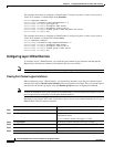
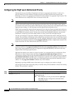
To display EtherChannel, PAgP, and LACP status information, use the privileged EXEC commands
described in
Table 34-4:
You can clear PAgP channel-group information and traffic counters by using the clear pagp
{channel-group-number counters | counters} privileged EXEC command.
You can clear LACP channel-group information and traffic counters by using the clear lacp
{channel-group-number counters | counters} privileged EXEC command.
For detailed information about the fields in the displays, see the command reference for this release.
Understanding Link-State Tracking
Link-state tracking, also known as trunk failover, is a feature that binds the link state of multiple
interfaces. For example, link-state tracking provides redundancy in the network when used with Flex
Links. If the link is lost on the primary interface, connectivity is transparently switched to the secondary
interface.
Note The switch must be running the metro IP access or metro access image to support link-state tracking.
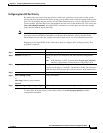
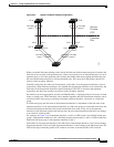
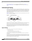
As shown in Figure 34-4, switches that could be Cisco ME 3400 switches are used as user-facing
provider edge (UPE) switches in a customer site at the edge of the provider network connected to a
customer premises equipment (CPE) switch. The UPE switches are connected to the provider edge (PE)
switches in the service provider (SP) network. Customer devices, such as clients, connected to the CPE
switch have multiple connections to the SP network. This configuration ensures that the traffic flow is
balanced from the customer site to the SP and the reverse. Ports connected to the CPE are referred to as
downstream ports, and ports connected to PE switches are referred to as upstream ports.
• UPE switch A provides links to the CPE through link-state group 1. Port 1 and port 2 are connected
to the CPE. Port 3 and port 4 are connected to PE switch A through link-state group 1.
• UPE switch B provides links to the CPE through link-state group 2. Port 1 and port 2 are connected
to CPE. Port 3 and 4 are connected to PE switch A through link-state group 2.
Ta ble 34-4 Commands for Displaying EtherChannel, PAgP, and LACP Status
Command Description
show etherchannel [channel-group-number {detail |
port | port-channel | protocol | summary}] {detail |
load-balance | port | port-channel | protocol |
summary}
Displays EtherChannel information in a brief, detailed, and
one-line summary form. Also displays the load-balance or
frame-distribution scheme, port, port-channel, and protocol
information.
show pagp [channel-group-number] {counters |
internal | neighbor}
Displays PAgP information such as traffic information, the
internal PAgP configuration, and neighbor information.
show lacp [channel-group-number] {counters |
internal
| neighbor}
Displays LACP information such as traffic information, the
internal LACP configuration, and neighbor information.