


9-12
Cisco ME 3400 Ethernet Access Switch Software Configuration Guide
OL-9639-06
Chapter 9 Configuring Interfaces
Configuring Ethernet Interfaces
This example shows how to create a multiple-interface macro named macro1 and assign all of the
interfaces in the range to a VLAN:
Switch# configure terminal
Switch(config)# define interface-range macro1 fastethernet0/1 - 2, gigabitethernet0/1 - 2
Switch(config)# interface range macro macro1
Switch(config-if-range)# switchport access vlan 20
Switch(config-if-range)# no shut
Switch(config-if-range)# end
This example shows how to enter interface range configuration mode for the interface-range
macro
enet_list:
Switch# configure terminal
Switch(config)# interface range macro enet_list
Switch(config-if-range)#
This example shows how to delete the interface-range macro enet_list and to verify that it was deleted.
Switch# configure terminal
Switch(config)# no define interface-range enet_list
Switch(config)# end
Switch# show run | include define
Switch#
Configuring Ethernet Interfaces
These sections contain this configuration information:
• Default Ethernet Interface Configuration, page 9-12
• Configuring the Port Type, page 9-14
• Configuring Interface Speed and Duplex Mode, page 9-15
• Configuring a Dual-Purpose Port, page 9-17
• Configuring IEEE 802.3x Flow Control, page 9-19
• Configuring Auto-MDIX on an Interface, page 9-20
• Adding a Description for an Interface, page 9-21
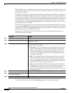
Default Ethernet Interface Configuration
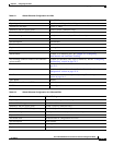
Table 9-1 shows the Ethernet interface default configuration for NNIs, and Table 9-2 shows the Ethernet
interface default configuration for UNIs and ENIs. For more details on the VLAN parameters listed in
the table, see
Chapter 11, “Configuring VLANs.” For details on controlling traffic to the port, see
Chapter 22, “Configuring Port-Based Traffic Control.”
Note To configure Layer 2 parameters, if the interface is in Layer 3 mode, you must enter the switchport
interface configuration command without any parameters to put the interface into Layer 2 mode. This
shuts down the interface and then re-enables it, which might generate messages on the device to which
the interface is connected. When you put an interface that is in Layer 3 mode into Layer 2 mode, the
previous configuration information related to the affected interface might be lost, and the interface is
returned to its default configuration.