


34-23
Cisco ME 3400 Ethernet Access Switch Software Configuration Guide
OL-9639-06
Chapter 34 Configuring EtherChannels and Link-State Tracking
Understanding Link-State Tracking
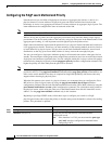
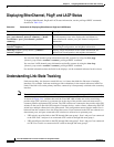
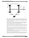
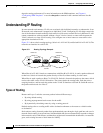
Figure 34-4 Typical Link-State Tracking Configuration
When you enable link-state tracking on the switch, the link state of the downstream ports is bound to the
link state of one or more of the upstream ports. After you associate a set of downstream ports to a set of
upstream ports, if all of the upstream ports become unavailable, link-state tracking automatically puts
the associated downstream ports in an error-disabled state. This causes the CPE primary interface to
failover to the secondary interface.
If the PE switch fails, the cables are disconnected, or the link is lost, the upstream interfaces can lose
connectivity. When link-state tracking is not enabled and the upstream interfaces lose connectivity, the
link states of the downstream interfaces remain unchanged. The CPE is not aware that upstream
connectivity has been lost and does not failover to the secondary interface.
An interface can be an aggregation of ports (an EtherChannel), a single physical port in access or trunk
mode, or routed ports. These interfaces can be bundled together, and each downstream interface can be
associated with a single group consisting of multiple upstream interfaces, referred to as a link-state
group.
In a link-state group, the link state of the downstream interfaces is dependent on the link state of the
upstream interfaces. If all of the upstream interfaces in a link-state group are in the link-down state, the
associated downstream interfaces are forced into the link-down state. If any one of the upstream
interfaces in the link-state group in the link-up state, the associated downstream interfaces can change
to or remain in a link-up state.
For example, in Figure 34-4, downstream interfaces 1 and 2 on UPE switch A are defined in link-state
group 1 with upstream interfaces 3 and 4. Similarly, downstream interfaces 1 and 2 on UPE switch B are
defined in link-state group 2 with upstream interfaces 3 and 4.
If the link is lost on upstream interface 3, the link states of downstream interfaces 1 and 2 do not change.
If upstream interface 4 also loses link, downstream interfaces 1 and 2 change to the link-down state. The
CPE switch stops forwarding traffic to PE switch A and starts to forward traffic to PE switch B.
CPE
UPE A
Port 3 Port 4 Port 3 Port 4
Port 1 Port 2
Port 2 Port 1
PE A
UPE B
PE B
Link-state
group 1
Link-state
group 1
Link-state
group 2
Link-state
group 2
Service
Provider
POP
Customer
Site
141683