


1-16
Cisco ME 3400 Ethernet Access Switch Software Configuration Guide
OL-9639-06
Chapter 1 Overview
Network Configuration Examples
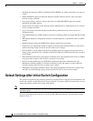
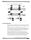
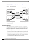
See Chapter 13, “Configuring IEEE 802.1Q and Layer 2 Protocol Tunneling,” for more information on
configuring these features.
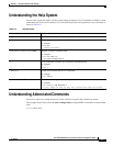
Figure 1-2 Layer 2 VPN Configuration
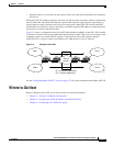
Multi-VRF CE Application
A VPN is a collection of sites sharing a common routing table. A customer site is connected to the
service-provider network by one or more interfaces, and the service provider associates each interface
with a VPN routing table, called a VPN routing/forwarding (VRF) table. Multiple VPN
routing/forwarding (multi-VRF) instances in customer edge (CE) devices (multi-VRF CE) allows a
service provider to support two or more VPNs with overlapping IP addresses.
Multi-VRF CE includes these devices:
• Customer edge (CE) devices provide customers access to the service-provider network over a data
link to one or more provider edge routers. The CE device advertises the site’s local routes to the
router and learns the remote VPN routes from the router. The Cisco ME 3400 switch can be a CE
device.
• Provider edge (PE) routers exchange routing information with CE devices by using static routing or
a routing protocol such as BGP, RIPv2, OSPF, or EIGRP. The PE is only required to maintain VPN
routes for directly attached VPNs. It does not need to maintain all of the service-provider VPN
routes. Each PE router maintains a VRF for each of its directly connected sites.
92997
CPE
VLAN 50-120
VLAN 35-60
SP Metro core
SP VLAN 5
SP VLAN 8
UPE
UPE
UPE
UPE
VLAN 50-120
CPE
CPE
CPE
Customer
VLAN 35-60
Corp A, site 1
Corp B, site 2
Corp A, site 2
Corp B, site 3
Corp B, site 1
Customer building
UPE = Cisco ME 3400 switch
CPE
Customer
VLAN 50-120
SP VLAN 8SP VLAN 8
SP VLAN 8SP VLAN 8
SP VLAN 5SP VLAN 5
Customer building
Customer building
Customer building