


8-7
Cisco WAN Modeling Tools Guide
OL-10426-01, Rev. A0
Chapter 8 NMT Map
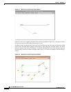
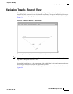
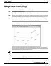
Panning the Map
Panning the Map
To move a map to a different position on the screen, move the cursor to a blank spot on the screen. Hold
down the middle mouse button while dragging the cursor in the direction you want the map to move.
When you release the mouse button, the nodes, links, and background map shift in that direction on
screen.
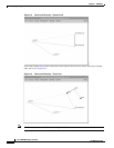
To return to the map to its original position, move the cursor to a blank spot on the map and click the
right mouse button.
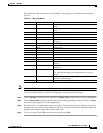
Map Color Coding
The map tool uses color coding to help you recognize important aspects of your network topology. The
color coding is described in Table 8-1.
Note The colors of the logical nodes (groups of nodes) and the links displayed with thick lines (multiple links)
are determined by the worst condition of the individual nodes or links that make up the set.
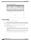
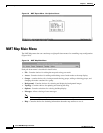
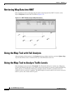
Controlling Map Displays in NMT
Map displays are controlled through the Report Menu in the NMT Main Menu. The Set Options screen
contains variables to control map output. (Figure 8-8).
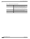
Table 8-1 Network Topology Map Color Coding
Color Node Link
Green Node is functioning normally (all
connections have been routed).
Link traffic is below the warning threshold.
Yellow Node is a hub node, and some of its feeders are
not shown.
Link traffic is above the warning threshold but
below the critical
threshold.
Red
Not all connections at this node could
route.
Link
traffic exceeds the critical threshold, or
link has failed.