


12-3
Cisco WAN Modeling Tools Guide
OL-10426-01, Rev. A0
Chapter 12 Cisco Network Designer Importer
CND PC Import Utilities
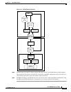
DBF2Cnd Operating Instructions
To run the DBF2Cnd utility, follow these steps:
Step 1 Click the SSI macro to start MS Excel.
Step 2 Create an Excel workbook with the following files:
1. a sites sheet— The Site sheet must have two columns:
–
Name - Site name, up to 10 characters,
–
Type - Chassis Part type, up to 19 characters.
The Hor and Ver columns are optional. Use them to position sites on the CND drawing. 0,0 is the
upper left coordinate. The positions will be stretched to scale. All sites but one must have at least
one non-zero coordinate for the coordinates to be used. Otherwise an auto-position algorithm is
used.
2. an options links sheet—The Link sheet must have two columns:
–
Site1—Site name for end one of the link.
–
Site2—Site name for end two of the link.
3. a Parts List sheet—The Parts List sheet must have two columns:
–
Site—Site name for the part
–
Model_No—The part to add QTY is an optional column, Use this if you want to enter more than
one part per line.
Note There is a template example of these files in c:\nmt\data\excel
Step 3 In the Tools menu, go to macro<macros<SSI!NMT_Unload’, and click run.
Step 4 Navigate to the directory where you wish to store the DBF files, and click save.
Note Ignore the message about other missing NMT files.
Step 5 Shut down CND if it is running.
Step 6 Click the dbf2cnd icon to launch the dbf2cnd utility. An MFC menu appears.
Step 7 In the MFC menu, select File<open and navigate to the directory containing your DBF.
Step 8 Open any file in the DBF directory. A pop up window displays sites, links, and part candidate counts.
Step 9 Click OK.