


4-6
Cisco WAN Modeling Tools Guide
OL-10426-01, Rev. A0
Chapter4 Configuration Tables and Fields
Links Table
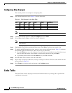
Configuring Sites Example
This section provides an example for configuring Sites.
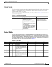
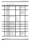
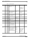
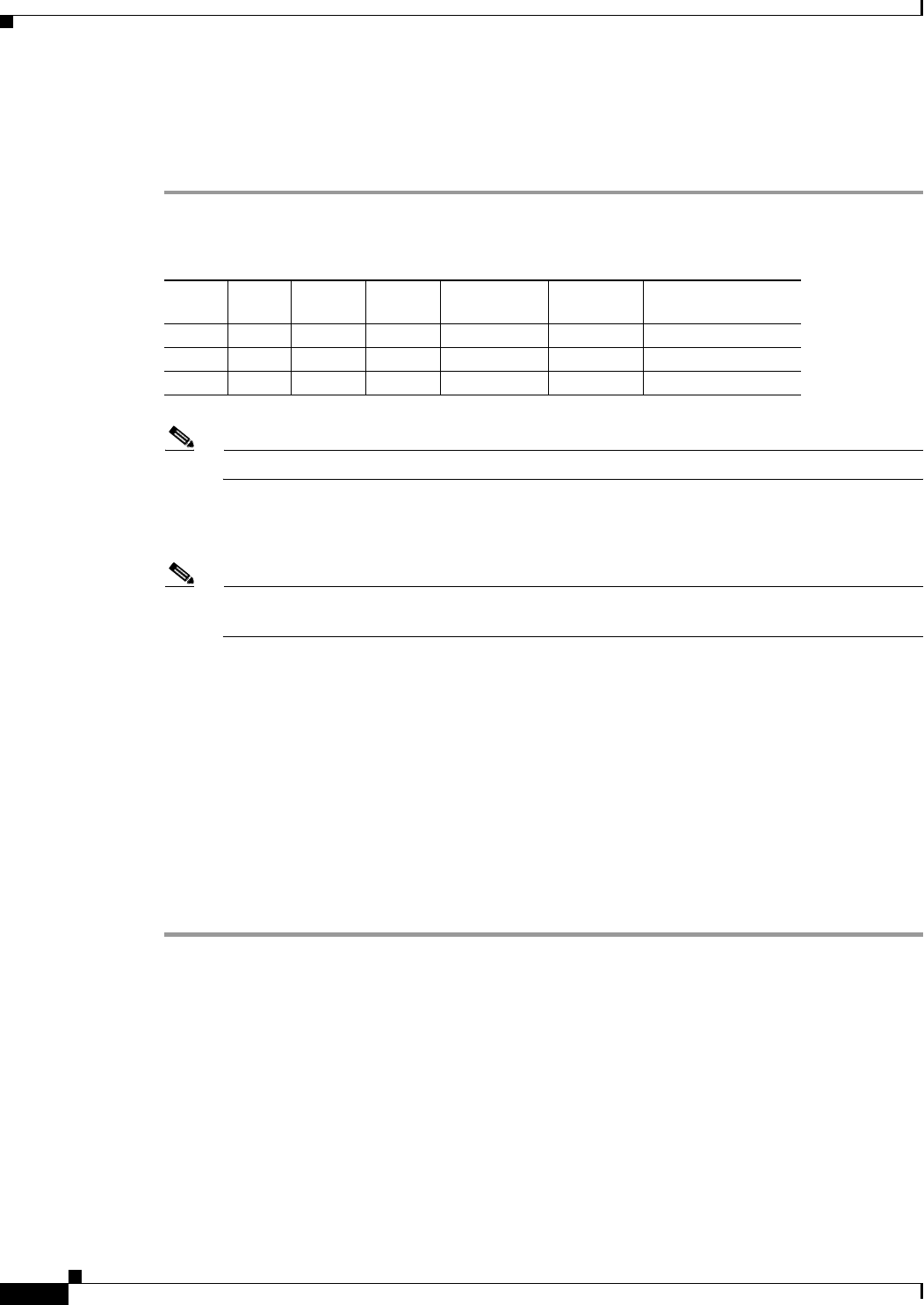
Step 1 Enter the information shown in Table 4-2 into the Sites table.
Note Except where noted in this table, each node uses default values.
Step 2 Use the left and right arrows to highlight Configure and press Enter.
Step 3 Select Sites and press Enter. A new sites table is displayed.
Note Select a menu choice by using the up and down arrow keys, or by typing the first letter of the
item selected.
Step 4 Highlight the Site field by pressing the Down arrow. Type Paris. You have now created a site.
Step 5 To modify the NMT default site values, cursor or tab to each of the fields listed in Table 4-2, and enter
the data that applies to the Paris site. There are two ways to enter data:
1. Press the Help key to see a list of choices. Lists of choices are available for most fields that accept
three or more non-numeric values. Make a selection using the cursor and press Enter.
2. Type directly into the field. Press the Delete key if you make a mistake.
Step 6 Press the down arrow to insert a new line in the table.
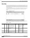
Step 7 Repeat Step 4 and Step 5 for Boston, and Step 4 and Step 5 for Denver. The Sites table should look like
the one shown in Figure 4-1.
Step 8 Press Escape to accept the entries and return to the Configure menu.
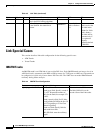
Links Table
The Links Table contains topological and cost information about every existing link or possible link
candidate in the network.
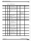
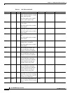
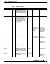
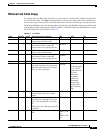
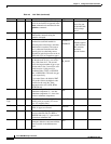
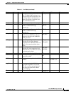
Table 4-2 Field Changes for the Sites Table
Site Type Power IGX
BC (Back
Card)
FC (Front
Card)
RLC (Redundant
Link Card)
Paris IGX D N E1 NTC Y
Boston IGX A Y T1 NTM N
Denver IGX A Y T3 BTM N