


4-10
Cisco WAN Modeling Tools Guide
OL-10426-01, Rev. A0
Chapter4 Configuration Tables and Fields
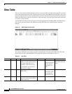
Link Special Cases
Link Special Cases
This section describes link table configuration for the following special cases:
• ATM Trunks
• Virtual Trunks
IMATM Trunks
An IMATM trunk is an ATM link of one to eight DS1 lines. Each IMATM trunk card uses a slot of an
AXIS shelf, and is connected to the BPX switch by means of a T3/E3 port on a BNI card. The trunk can
be configured so it fails only if more than n DS1 lines fail. The NMT does not model IMATM trunk
resiliency during failure analysis.
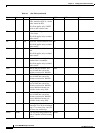
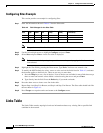
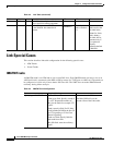
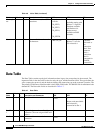
AW 5040 O Administrative weight used for least
cost in the PNNI routing algorithm.
AW
Comment A free field comment field. Translates
to the WANDL link label field if
present.
COMMENT
Not available
until sv+ Release
9.0.
The comment
field is used as the
link label in the
bblink file. If this
field is blank, a
link label will be
generated only if
it is required to
uniquely
determine the link
in WANDL.
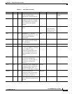
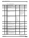
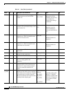
Table 4-3 Link Table (continued)
Field Defaults Notes Description and Comments DBF CET TPI
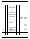
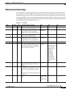
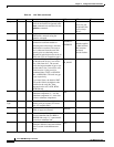
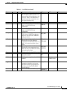
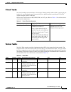
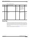
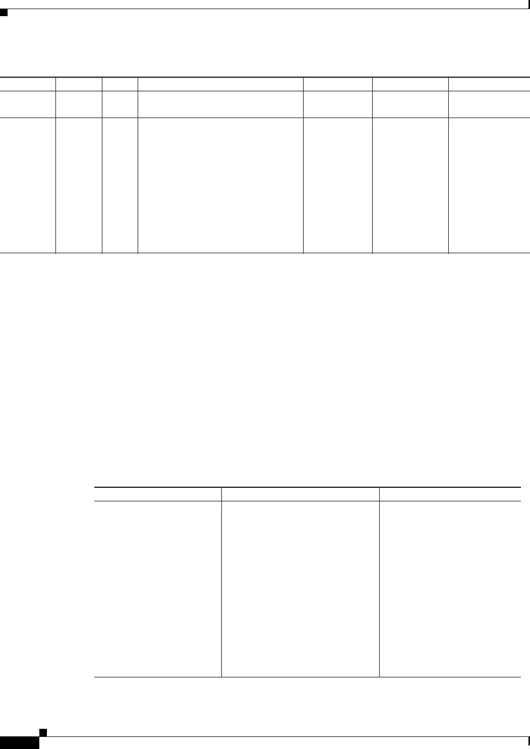
Table 4-4 IMATM Trunk Configuration
Topic Required Settings Comments
Specifying an IMATM Trunk Links table
Trunk (type) field: Specify a trunk of
T1 or E1. Prepend the number of
DS1s for the trunk, for example 5:T1
or 8:E1.
Trunk (capacity) field: For E1 links,
specify number of DS0 in the line: 30
for CCS signalling or 32 for Clear
Channel signalling.
Trunk card field: Specify IMA for
both trunk front cards.
IMA_RD field: enter the resiliency
degree.
Both sites must be BPX.
The IMA_RD field is on the
second screen of the Links table.