


Creating Monitor Pictures
A.1 Interactive Definition of a Monitor Picture
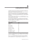
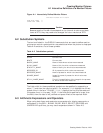
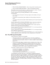
Figure A–1 Interactively Defined Monitor Picture
THE TEST PICTURE AT 11:49:24
SOME DATA ITEM: 0
OTHER DATA ITEM: 0
Caution
Because monitor file definitions depend on the internal structure and data
items of RTR, they may need to be changed for future versions of RTR.
A.2 Substitution Symbols
The text and labels in the DISPLAY commands that are used to define monitor
pictures can contain symbols which are substituted when the picture is displayed.
Table A–2 contains a list of these symbols.
Table A–2 Substitution symbols
Symbol Description
$TIME Current time
$DATE Current date
$NODE_NAME Name of node where values were measured
$LINK_NAME Name of link for which values were measured
$FACILITY_NAME Name of facility for which value was measured
$PROCESS_ID ID of process for which value was measured
$PROCESS_NAME Name of process for which value was measured
$IMAGE_NAME Image file name of process for which value was
measured
$FULL_IMAGE_NAME The full file specification of the image for the process
for which values were measured
The field width for these predefined symbols can be specified by appending a
colon (":") and then the required width. For example,
$TIME
displays the current
system time in the form "10:34:03",
$TIME:5
displays the first five characters of
the system time, in this case, "10:34". If the field width specified is larger than
the field, then the data is left justified and space filled to the required width.
A.3 Arithmetic Expressions and Operators
When using data items and constants as parameters for display commands, or
as Booleans in the BELL, BLANK, BLINK, BOLD, SELECT, REVERSE and
UNDERLINE qualifiers, you may use the operators shown in Table A–3.
Creating Monitor Pictures A–3