


Installing System Components 101
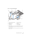
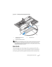
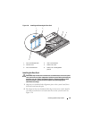
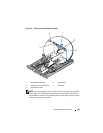
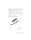
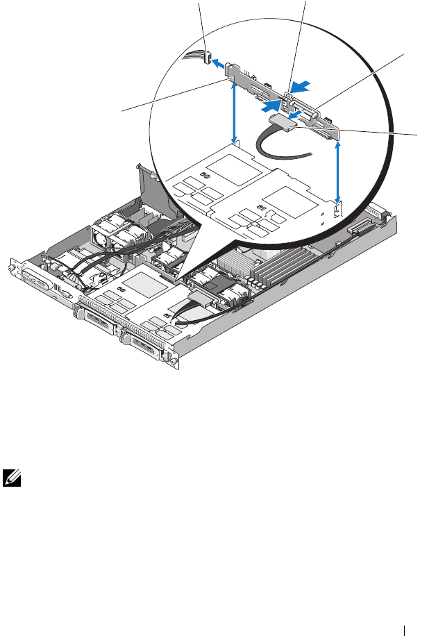
Figure 3-17. Removing and Installing the Backplane
NOTE: In the preceding figure, the 12C cable is shown connecting over the control
panel cabling. This cable should be routed under the control panel cable and the
internal USB key connector. The 12C cable seats in a cable guide clip that is directly
beneath the control panel connector.
1 backplane securing slot 2 power cable
3 backplane center release latch 4 backplane
5 SAS interface cable
3
1
2
5
4