


Installing System Components 85
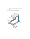
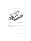
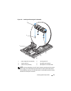
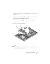
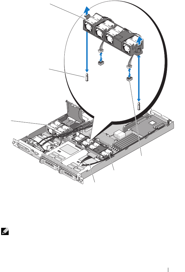
Figure 3-10. Installing and Removing the Fan Assembly
NOTE: In the preceding figure, the 12C cable is shown connecting over the control
panel cabling. This cable should be routed under the control panel cable and the
internal USB key connector. The 12C cable seats in a cable guide clip that is directly
beneath the control panel connector.
1 power supply fan bay assembly 2 securing posts (2)
3 release levers (2) 4 fan cables and connector
5 system fan bay assembly 6 SAS expansion card data cable
3
2
6
5
1
4