


72 Installing System Components
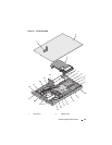
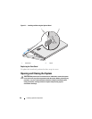
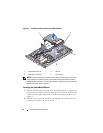
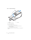
Figure 3-5. Installing and Removing the System Board Shroud
NOTE: In the preceding figure, the 12C cable is shown connecting over the control
panel cabling. This cable should be routed under the control panel cable and the
internal USB key connector. The 12C cable seats in a cable guide clip that is directly
beneath the control panel connector.
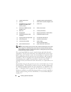
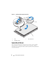
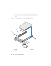
Installing the System Board Shroud
1
Align the shroud using both ends of the numbered fan bays as a guide and
locate the three tab slots on the left and right sides of the fan modules and
a third tab at the upper right corner in front of the memory modules. See
Figure 3-5.
2
Push the system board shroud down until all edges are seated in the slots,
securing the shroud to the system board.
1 system board shroud 2 tabs (3)
3 SAS cable connector 4 tab slots (3)
1
4
2
3