


Installing System Components 115
6
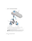
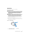
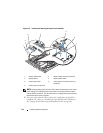
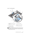
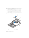
Disconnect the display module cable from the control panel board. See
Figure 3-22.
7
Remove the three screws that secure the control panel board to the system
chassis and remove the board. See Figure 3-22.
8
Remove the display module:
a
Insert the end of paper clip into the hole on the right side of the
display module and gently pry off the label.
b
Using a T10 Torx driver, remove the two screws that secure the display
module to the system chassis.
c
Remove the display module from the chassis cutout.
Installing the Control Panel Assembly
1
Insert the display module into the chassis cutout and secure with the two
Torx screws.
2
Affix the display module label to the display module.
3
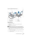
Install the control panel board in the system chassis and secure with the
three Phillips screws. See Figure 3-22.
4
Connect the display module cable to the control panel board. See
Figure 3-22.
5
Connect the internal USB key cable and, if applicable, the hard-drive
backplane 12C cable. See "Installing the Optional Internal USB Memory
Key" on page 90 and "Installing the Backplane Board" on page 102.
6
Connect the control panel cable to the control panel board. See
Figure 3-22.
7
Close the system. See "Opening and Closing the System" on page 68.
8
Reconnect the system to the power source and turn on the system and
attached peripherals.
9
If applicable, install the bezel.