


83
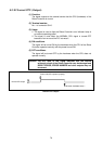
4.2.14 Error No. (Output)
(1) Function
When an error occurs, the signal outputs the error number in a 3-digit (12-
bit) hexadecimal code.
(2) Terminal numbers
No.17 to No.28 of connector CN10.
(3) Usage
The signal is used to display an error number on the external device.
(4) Output conditions
The signal will be output when an error occurs.
(5) Clear conditions
The signal will be cleared when CLEAR ROBOT FAILURE and
OPERATION PREPARATION START signals are inputted or by operating
the Cancel key of the operating panel or the teach pendant. When this
signal is cleared, all states will become OFF (0).
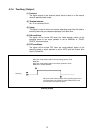
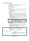
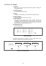
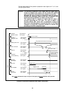
(6) Hexadecimal codes
See the following figure.
×××× → 0 סס → 5 ¡×¡×→ A
××ס → 1 ס¡×→ 6 ¡×¡¡ → B
×ס×→ 2 ס¡¡ → 7 ¡¡×× → C
×ס¡ → 3 ¡××× → 8 ¡¡×¡ → D
ס×× → 4 ¡×ס → 9 ¡¡¡×→ E ¡⋅⋅⋅ON
¡¡¡¡ → F ×⋅⋅⋅⋅OFF
Hexadecimal Codes
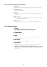
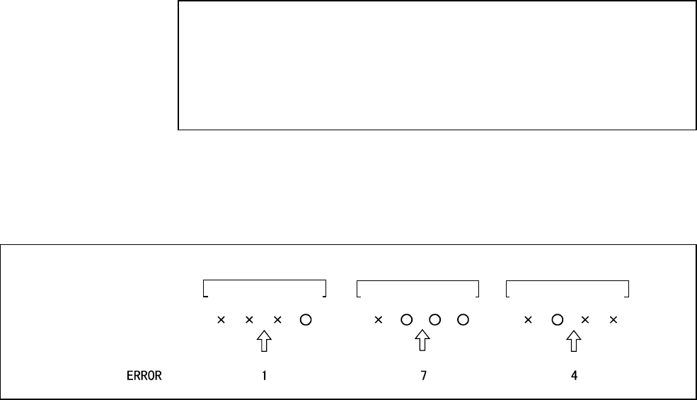
The figure below shows an example of error number output, when
ERROR174 (overload error with the fourth axis) occurs.
28 27 26 25
24 23 22 21
20 19 18 17
Terminal No.
(connector CN10)
Example of Error Number Output
Hundreds of error No.
Tens of error No. Units of error No.