


130
Chapter 6
Connector Pin Assignment and I/O Circuits
(PNP type)
This chapter explains the connector pin assignment and circuits of PNP type (sink
input and source output) on an I/O board.
For an NPN type (source input and sink output), refer to Chapter 5, "Connector Pin
Assignment and I/O Circuits (NPN type)."
6.1 Connector Pin Assignment (PNP type)
This section describes the pin assignment of connectors on the robot controller. The
signals and pin assignments of output connector CN10 and input connector CN8 are
differently defined in standard mode and compatible mode. As for other connectors,
the definitions of pins are common to standard mode and compatible mode.
6.1.1 Connector Pin Assignment Common to Both Modes (PNP type)
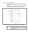
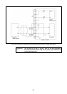
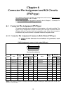
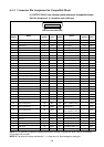
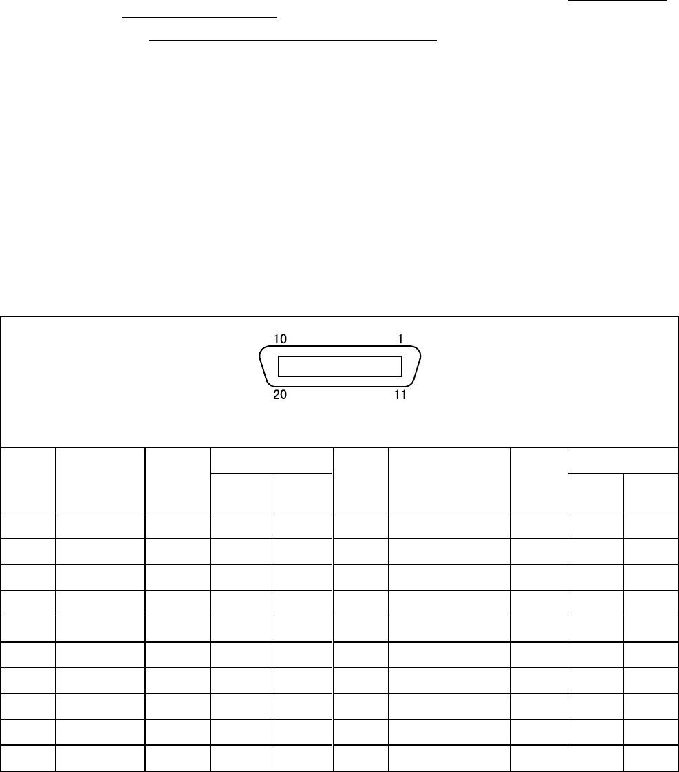
(1) HAND I/O CN9: Connector for end-effector I/O (common to both
modes)
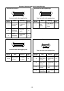
CN9 Pin Assignment, common to both modes (PNP type)
View from the cable side
Wire color Wire color
Terminal
No.
Name
Port
number
Standard
High
strength
Terminal
No.
Name
Port
number
Standard
High
strength
1 Hand output 64 Black Blue 11 Hand Input 50 Pink White
2
Hand output
65 Brown Yellow 12
Hand Input
51 Pink White
3
Hand output
66 Black Green 13
Hand Input
52 White White
4
Hand output
67 Brown Red 14
Hand Input
53 White White
5 Hand output 68 Red Violet 15 Hand Input 54 White White
6
Hand output
69 Orange Blue 16
Hand Input
55 White Brown
7
Hand output
70 Yellow Yellow 17
Power E0V for Hand
White Brown
8
Hand output
71 Green Green 18
Power E24V for Hand
White Brown
9 Hand input 48 Blue Red 19 Not connected White Brown
10
Hand input
49 Violet Violet
20
Not connected
White Brown
NOTE: The optional I/O cable for the above connector consists of twisted pair wires--pairs of #1 and #11, #2
and #12,…#10 and #20.