


Index
Auto Mode (Output) ............................................ 28
, 71
CAL Complete (Output)............................................ 73
Clear Robot Failure (Input) ..................................... 103
Command and Data Areas......................................... 48
Command Execution I/O Signals Dedicated to Standard
Mode.......................................................................... 45
Command Processing Complete (Output) ................. 50
Compatible Mode .......................................... 14
, 23, 69
Connector Pin Assignment and I/O Circuits (PNP type)
................................................................................. 130
Connector Pin Assignment I/O Circuits (NPN type).....
................................................................................. 110
Continue Start (Input).............................................. 105
Continue Start Permitted (Output)....................... 36
, 84
Control System Configuration................................... 12
Controller I/O Circuits..................................... 116
, 136
Controller I/O Connectors ............................... 128
, 148
Controller Specifications ............................................. 7
Dead Battery Warning (Output)........................... 35
, 82
Emergency Stop (Output from a contact) ............ 37
, 85
Emergency Stop Output Circuit....................... 124
, 144
Enable Auto (Input)............................................. 39
, 87
Error No. (Output) ..................................................... 83
Error Read ................................................................. 57
External Mode (Output)....................................... 29
, 74
External Speed and Acceleration Setting................... 56
HAND I/O CN9: Connector for end-effector I/O
(common to both modes)................................. 110
, 130
Hand-Input Circuits ......................................... 118
, 138
Hand-Output Circuits....................................... 122
, 142
I/O Commands........................................................... 52
I/O POWER CN7: Power connector for I/O
(common to both modes).................................111
, 131
I/O Power Connector....................................... 126
, 146
I/O Read..................................................................... 64
I/O Signals................................................................. 22
I/O Type Variable....................................................... 24
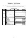
I/O Wiring................................................................ 150
I/O Write....................................................................63
INPUT CN8: User-/System-input connector
(compatible mode) ........................................... 115
, 135
INPUT CN8: User-/System-input connector
(standard mode) .............................................. 113
, 133
Instantaneous Stop (All Tasks) (Input) ..............42, 102
Interface.....................................................................14
Interrupt Skip (Input).........................................43
, 104
Mode Switching.........................................................60
Normal CPU (Output)..........................................32
, 79
NPN type .................................................................110
Operation Preparation Start (Input)............................88
OUTPUT CN10: User-/System-output connector
(compatible mode) ........................................... 114
, 134
OUTPUT CN10: User-/System-output connector
(standard mode) ............................................... 112
, 132
PNP type..................................................................130
Processing I/O Commands......................................... 46
Program No. Select (Input)........................................90
Program Operation Command ...................................53
Program Reset (Input)................................................98
Program Start (Input)................................................. 92
Program Start Reset (Output).....................................76
Robot Controller Components .....................................4
Robot Controller I/O Connectors............................. 148
Robot Failure (Output)......................................... 33
, 80
Robot Initialization Complete (Output).....................27
Robot Power ON Complete .......................................70
Robot Stop (Input) .....................................................40
Robot Stop and Enable Auto Input Circuits..... 119
, 139
Robot Warning (Output) ......................................34
, 81
Robot-in-operation (Output) ................................31
, 77
RS232C.................................................................... 111
RS232C CN1: RS232C connector...........................131