


148
6.3 Wiring Notes for Robot Controller I/O Connectors (PNP
type)
After the wiring of the controller's I/O connectors is completed, check the following
before turning ON the power:
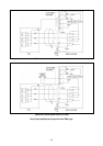
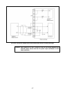
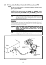
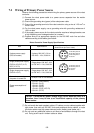
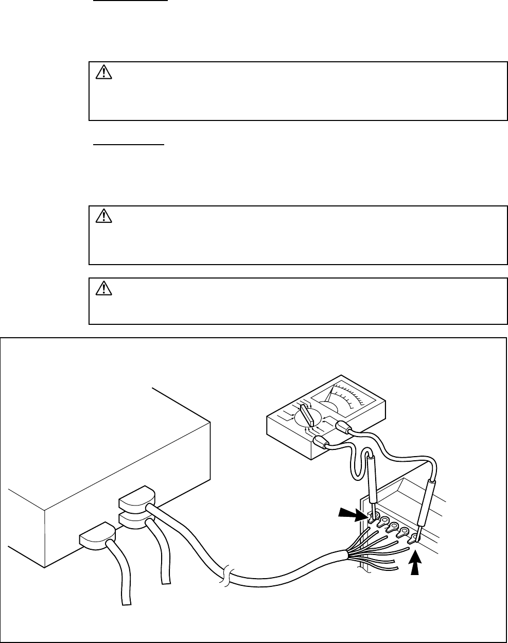
Check point (1)
Using a circuit tester, check across the "+24V terminal" and "0V terminal" of each
connector and across the "E24V terminal" and the "E0V terminal" to see that there
is no continuity. See the figure below and the table given on the next page.
Caution: If the connector wiring between the robot controller's "+24V
terminal" and "0V terminal" and between the "E24V terminal" and
the "E0V terminal" is shorted, damage to the power circuit of the
Robot Controller will result.
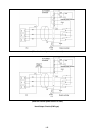
Check point (2)
Using a circuit tester, check across "each signal Output terminal" and "+24V terminal"
or "E24V terminal" of each connector to see that there is no continuity. See the figure
below and the table given on the next page.
Caution: If the wiring between "each signal Output terminal" and "+24V
terminal" or "E24V terminal" of each connector is shorted,
damage to the Output circuit and power circuit of the robot
controller will result.
Caution: Wind adhesive vinyl tape around all ends of the unconnected
wiring of each connector to prevent them from contacting other
wiring and parts, which results in shorting.
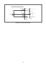
Robot
controlle
r
Circuit tester
“+24V terminal” and
“E24V terminal” of the
controlle
r
“0V terminal” and
“E0V terminal” of the
controlle
r
External
device
Checking Example