


1
Chapter 1
General Information about RC5 Controller
The RC5 controller is available in several models which differ in detailed
specifications to match robot models of
**
-D/-E series.
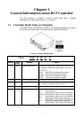
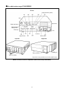
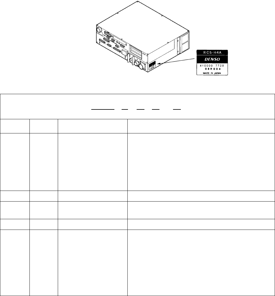
1.1 Controller Model Name on Nameplate
The model name of the controller is printed on the nameplate attached to the side of
the controller as shown below. The model name is coded as listed below.
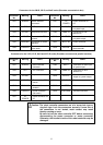
Coding of Controller Model Name
RC5 - VSE 6 B A - P
(a) (b) (c) (d) (e)
Position
Code
sample
Denotes: Coding
(a) VSE Robot model name VM: VM-D, VS: VS-D, VSE: VS-E, VC: VC-E,
H: HM/HS-D, HSE: HS-E, HME: HM-E, HC: HC-D,
XYC:XYC-D
EAH: HM/HS-D with extended-joint support
EAHC: HC-D with extended-joint support
EAXYC: XYC-D with extended-joint support
EAVS: VS-D with extended-joint support
(b) 6 No. of controllable axes 4: 4 axes, 5: 5 axes, 6: 6 axes
(c) B Engineering symbol 1 A: Encoders connected via parallel interface to CN13
B: Encoders connected via bus to CN12
(d) A Engineering symbol 2 Blank or A
(e) P Types Blank: I/O of NPN type
P: I/O of PNP type
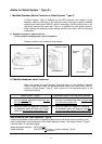
AN: Robot System “Type A” and I/O of NPN type
(Note: For Robot System “Type A” refer to next page.)
AP: Robot System “Type A” and I/O of PNP type
BN: Global type (:Dual emergency stop type +
Robot System “Type A”) and I/O of NPN type
BP: Global type (:Dual emergency stop type +
Robot System “Type A”) and I/O of PNP type
Nameplate
(Sample)