


114
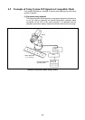
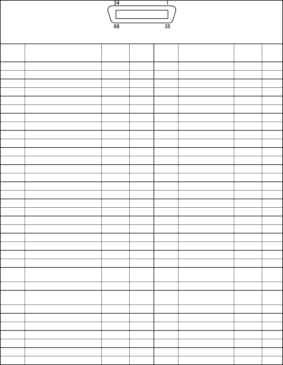
5.1.3 Connector Pin Assignment in Compatible Mode
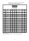
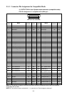
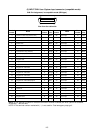
(1) OUTPUT CN10: User-/System-output connector (compatible mode)
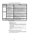
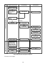
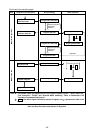
CN10 Pin Assignment, in compatible mode (NPN type)
View from the cable side
Terminal
number
Name
Port
number
Wire
color
Terminal
number
Name
Port
number
Wire
color
1 Normal CPU 72 Black 35 User output 106 Pink
2 Robot-in-operation 73 Brown 36 User output 107 Pink
3 Robot failure 74 Red 37 User output 108 Pink
4 Auto mode 75 Orange 38 User output 109 Pink
5 External mode 76 Yellow 39 User output 110 Pink
6 Program start reset 77 Black 40 User output 111 White
7 Not used. 78 Brown 41 User output 112 White
8 Not used. 79 Red 42 User output 113 White
9 Robot power ON complete 80 Orange 43 User output 114 White
10 Servo ON 81 Yellow 44 User output 115 White
11 CAL complete 82 Green 45 User output 116 White
12 Teaching 83 Blue 46 User output 117 White
13 Single-cycle complete 84 Violet 47 User output 118 White
14 Dead battery warning 85 Gray 48 User output 119 White
15 Robot warning 86 Pink 49 User output 120 White
16 Continue start permitted 87 Black 50 User output 121 Gray
17 Error units bit 0 88 Black 51 User output 122 Violet
18 Error units bit 1 89 Brown 52 User output 123 Violet
19 Error units bit 2 90 Red 53 User output 124 Violet
20 Error units bit 3 91 Orange 54 User output 125 Violet
21 Error tens bit 0 92 Yellow 55 User output 126 Violet
22 Error tens bit 1 93 Green 56 User output 127 Violet
23 Error tens bit 2 94 Blue 57 Not connected Violet
24 Error tens bit 3 95 Gray 58 Not connected Violet
25 Error hundreds bit 0 96 Pink *59
[ Power supply for Robot
stop 1 (Internal +24V) ]
Violet
26 Error hundreds bit 1 97 Brown *60 [ Robot stop 1 ] Gray
27 Error hundreds bit 2 98 Red *61
[ Power supply for Robot
stop 2 (Internal +24V) ]
Gray
28 Error hundreds bit 3 99 Orange *62 [ Robot stop 2 ] Gray
29 SS mode 100 Yellow *63 [ Emergency stop (+) ] Gray
30 Not used. 101 Green *64 [ Emergency stop (-) ] Gray
31 Not used. 102 Blue 65 Emergency stop 2 (+) Gray
32 Not used. 103 Pink 66 Emergency stop 2 (-) Gray
33 User output 104 Black *67 [ Deadman switch (+) ] Blue
34 User output 105 Brown *68 [ Deadman switch (-) ] Blue
NOTE 1: The optional I/O cable for the above connector consists of twisted pair wires--pairs of #1 and #35,
#2 and #36, #34 and #68.
NOTE 2: The terminal number marked with ( * ) is used only for “Dual emergency stop type”.