135
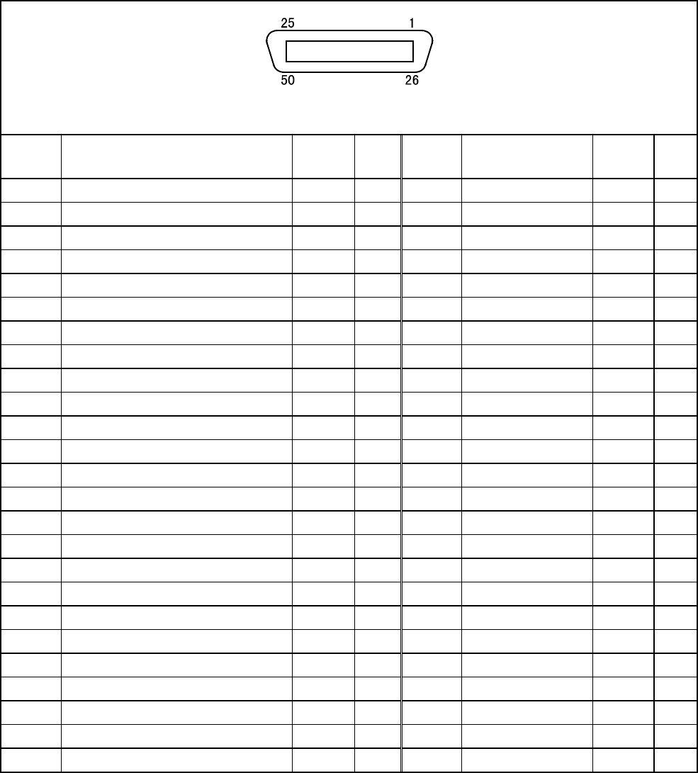
(2) INPUT CN8: User-/System-input connector (compatible mode)
CN8 Pin Assignment, in compatible mode (PNP type)
View from the cable side
Terminal
number
Name
Port
number
Wire
color
Terminal
number
Name
Port
number
Wire
color
*1 Power for robot stop (internal +24V) - Black 26 User input 21 Pink
*2 Robot stop - Brown 27 User input 22 Pink
3 Power for Enable Auto
(internal +24V) - Red 28 User input 23 Pink
4 Enable Auto - Black 29 User input 24 White
5 Step-stop (all tasks) 0 Brown 30 User input 25 White
6 Continue start 1 Red 31 User input 26 White
7 Instantaneous stop (all tasks) 2 Orange 32 User input 27 White
8 Operation preparation start 3 Yellow 33 User input 28 White
9 Interrupt skip 4 Green 34 User input 29 White
10 Program start 5 Blue 35 User input 30 White
11 Program No. select bit 0 6 Violet 36 User input 31 White
12 Program No. select bit 1 7 Black 37 User input 32 Gray
13 Program No. select bit 2 8 Brown 38 User input 33 Gray
14 Program No. select bit 3 9 Red 39 User input 34 Gray
15 Program No. select bit 4 10 Orange 40 User input 35 Gray
16 Program No. select bit 5 11 Yellow 41 User input 36 Gray
17 Program No. select bit 6 12 Green 42 User input 37 Gray
18 Program No. select odd parity bit 13 Blue 43 User input 38 Gray
19 Motor power ON 14 Violet 44 User input 39 Gray
20 CAL execution 15 White 45 User input 40 Gray
21 Reserved 16 Pink 46 User input 41 Gray
22 SP100 17 Black 47 User input 42 Violet
23 Switch Ext Mode 18 Brown 48 User input 43 Violet
24 Program reset 19 Red 49 User input 44 Violet
25 Clear robot failure 20 Orange 50 User input 45 Violet
NOTE 1: The optional I/O cable for the above connector consists of twisted pair wires--pairs of #1 and
#26, #2 and #27,…#25 and #50.
NOTE 2: The terminal number marked with ( * ) is not used for “Dual emergency stop type”.


