Softing Linking Device –
Manual for Configuration, Installation and Maintenance
Hardware Installation
V1.31 page 11 of 85
Stahl. You will find this manual on the CD-ROM or on the internet web page http://www.r-
stahl.com
2.6 FF H1 fieldbus connection
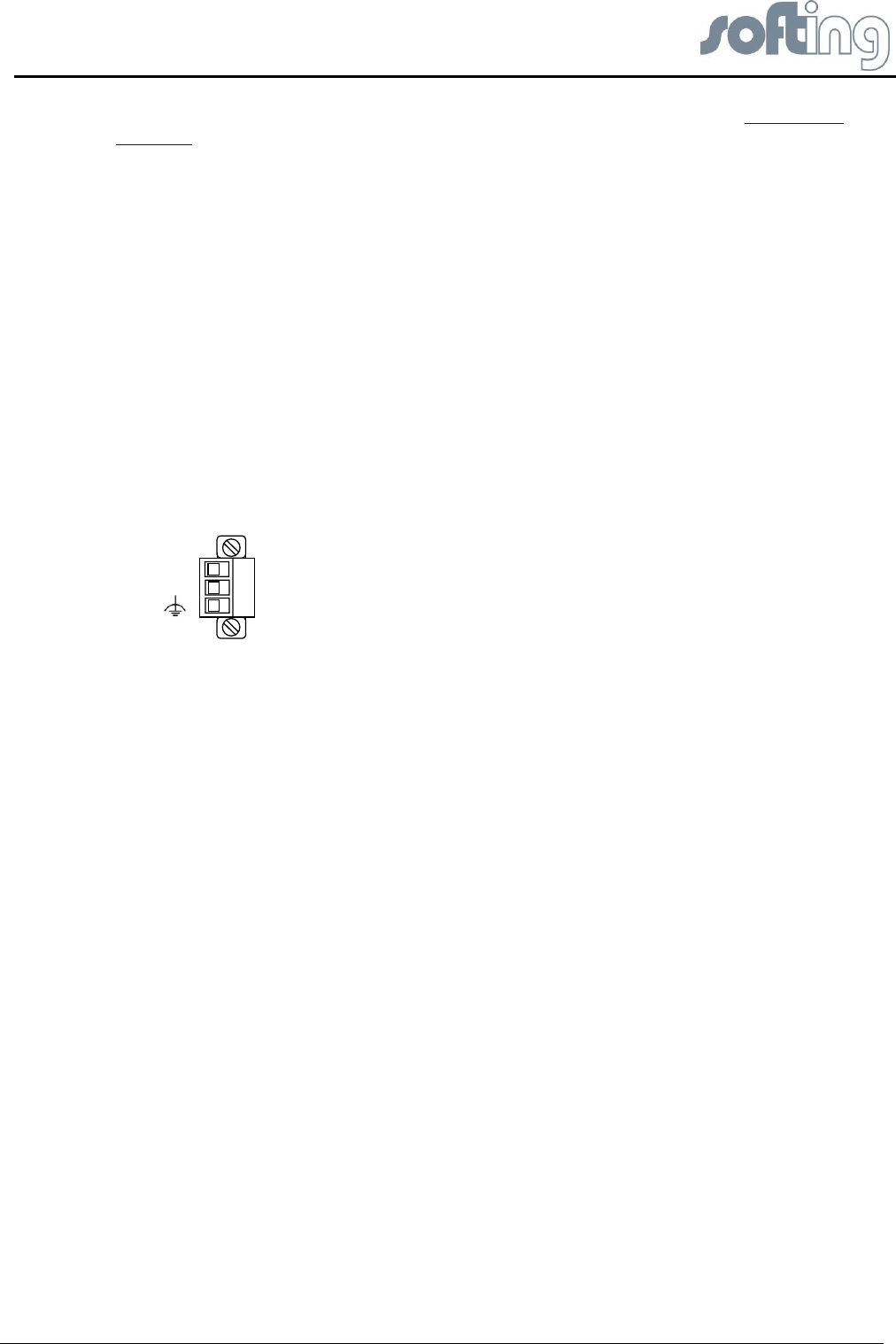
The fieldbus terminals are mounted in 4 sets of three terminals for the positive and negative
conductors and a shield (FF1 – FF4). Although the Linking Device is not polarity sensitive,
other components in the segment such as junction blocks may require correct polarity.
With 3-pole terminal blocks, up to 4 separate fieldbus segments can be connected. The FF-
H1 interfaces comply with type 114 of the FF physical layer profile, which is characterized by
● standard power signalling and voltage mode
● separately powered operation (galvanically isolated) no intrinsic safety
● the fieldbus cables +/- can be interchanged.
● wire diameter: 0.14 - 1.5 mm2, AWG 28-16
● replacement parts for the terminal block can be obtained from Phoenix-Contact
(http://www.phoenixcontact.com/) as part type MC 1,5/3-STF-3,81 BK AU.
+
-
Fig 2.6-1 Pin assignment 3-pole terminal block for FF H1 Connections
2.7 FIM-110 FF - The pre-wired Installation of the FG-110 FF
The FIM-110 FF has an IP-65 housing.
The upper cover provides access to single parts like
● the Linking Device FG-110 FF,
● the RS-232 / RS-485 converter,
● the fieldbus power conditioners/terminators,
● the power supply board and ground terminals.
The enclosure cover provides access to the terminal blocks. To open either cover of the
enclosure, use a ¼ inch blade screwdriver to remove the appropriate screw on the unhinged
side of the enclosure
The Linking Device is intended for mounting in a control cabinet. One of the favorite
possibilities is the FIM (SOFTING Foundation Fieldbus Interface Module FIM 110)


