Softing Linking Device –
Manual for Configuration, Installation and Maintenance
Hardware Installation
V1.31 page 9 of 85
2.3 Power Supply
The Linking Device is powered by 24 V DC. The power supply plug connector is included in
the delivery. The power supply socket connector on the front panel is labeled DC 24V-.
L+
M
Fig 2.3-1 Linking Device Power Supply
The two power supply terminals are labeled L+ and M. L+ must be connected to 24V and M
to 0V. The two terminals are provided with an internal reverse-polarity protection. The
functional ground terminal is labeled with the symbol and must be connected to the
protective ground. For use in an environment that is highly subject to electromagnetic
interference, an additional ground connection can be provided at the grounding screw below
the "LAN" connector.
Proper grounding is a prerequisite for compliance with the EMC directives and for ensuring
proper operation.
The power supply is connected to the plug connector via flexible wires with a cross section of
0.75 to 1.5 mm². The ground connection wire must have a cross section of 1.5 mm.
The Linking Device has an internal safety fuse which blows if an over voltage (of approx.
30V or higher) occurs in the power supply or if a fault occurs in the device. The safety fuse
can only be replaced by the device manufacturer.
The starting current of the Linking Device may be up to 3A. The power supply
must provide this starting current in compliance with the voltage range to ensure a
safe start-up. Replacement Part for this connector is Phoenix Contact MSTB2,5/3-
STF-5,08 BK AU.
2.4 Ethernet Port
The Linking Device is equipped with one 10/100 Base-T Ethernet interface receptacle.
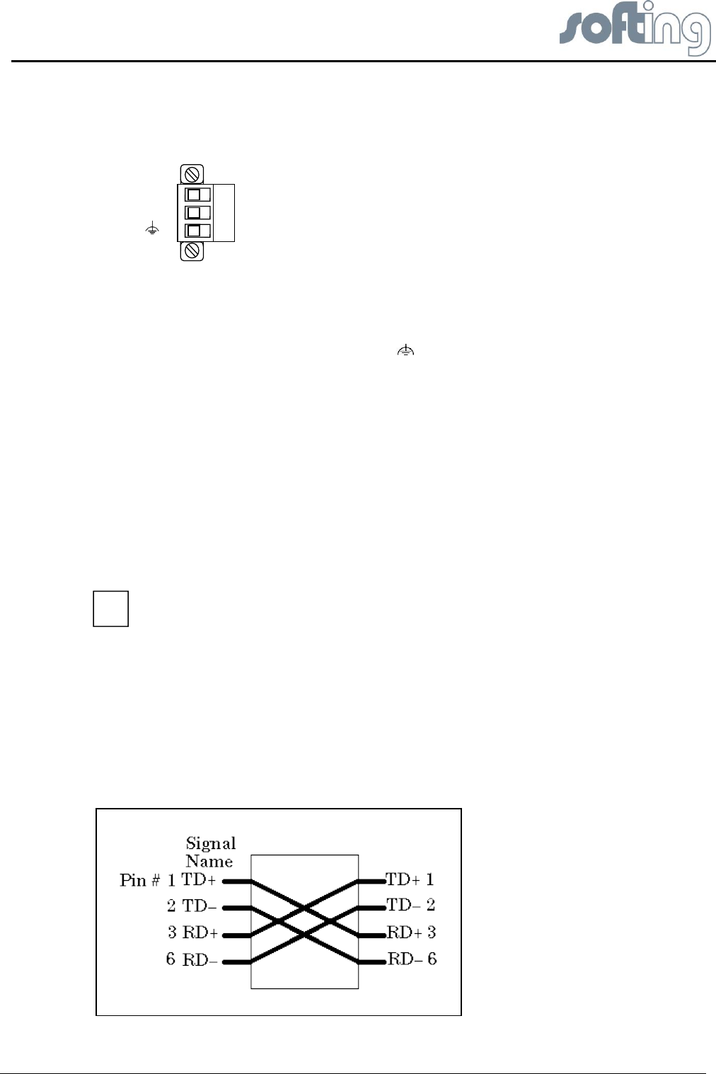
Connect the Linking Device to the PC that will be used for configuration, if it is possible using
an existing Ethernet Hub, Switch or Router. If you want to connect your PC to the Linking
Device directly do it with a crossover cable.
Fig 2.4-1 Crossover cable pinout
i


