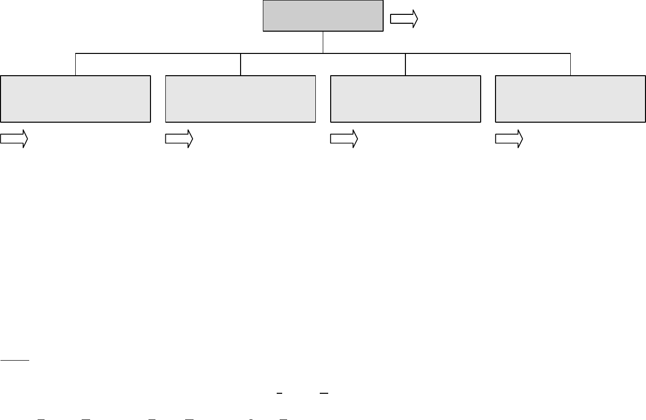
2 Structure of Menus
90003482(2) [NGA-e (MLT-Software 3.2.X)] 07/98
NGA 2000
2 - 1
Notes:
* M
enu lines ending with three points (...) are followed by submenus with further functions and set-ups.
*
All set-ups in the menu "Basic controls" are valid for the
analyzer module (AM).
*
At each menu point of the "Expert configuration" and "System configuration" you can find which functionality will be set up:
AM (A
nalyzer
M
odule), CM (
Control M
odule), I/O (
Input-/O
utput Module).
-
Calibration procedure
status...
-
Zero calibration of all
ranges
-
Span calibration of the
current range
-
Current gas valve setting:
- Zero gas flow
- Span gas flow
- Sample gas flow
- Test gas flow
- Closing all valves
- Analyzer module
controls... (AM)
- I/O module controls...
(I/O's: SIO, DIO)
- Analyzer module setup...
(AM)
- I/O module setup...
(Other micro processor
controlled I/O's)
- System calibration... (CM)
- Diagnostic menus...
(AM, CM, I/O's: SIO, DIO
and other I/O's)
- Date and time... (CM)
- Security codes...
(Lock of each level)
- Network module binding...
(AM, CM, I/O's: SIO, DIO
and other I/O's)
- System reset... (CM)
- System modules... (CM)
- System tag (CM)
- Display controls of the
front panel LCD
- Front panel control
(number of digits)
- Auxiliary lines
(for the
single component display)
Main Menu
Analyzer module
calibration & basic
controls... (AM)
Analyzer and I/O-
module expert
configuration...
System configuration
and diagnostics...
Display controls...
Section 4 Section 5 Section 6 Section 7
Section 3.8


