


S1C63000 CORE CPU MANUAL EPSON 19
CHAPTER 2: ARCHITECTURE
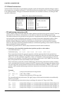
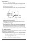
• Accessing for addresses 0000H to 003FH
Data in this area is used for a relative address by the "JR [addr6]" and "CALR [addr6]" explained in
Section 2.2.3. This area is suitable for setting up various flags and counters since the bit operation
instructions (CLR, SET, TST) and increment/decrement instructions (INC, DEC) are provided for
accessing this area.
• Accessing for addresses FFC0H to FFFFH (I/O memory area)
The bit operation instructions (CLR, SET, TST) are provided for accessing this area. Therefore, control
bits in the I/O memory can be operated simply.
Examples:
CLR [0xFFC0],0 ...Clears the D0 bit in the I/O memory address FFC0H to "0"
SET [0xFFD2],3 ...Sets the D3 bit in the I/O memory address FFD2H to "1"
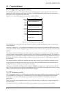
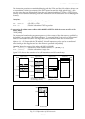
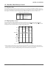
2.3.3 Stack and stack pointer
The stack is a memory that is accessed in the LIFO (Last In, First Out) format and is allocated to the RAM
area of the address 0000H to 03FFH. The stack area can be set from an optional address (toward the lower
address) using the stack pointer.
The S1C63000 contains two stack pointers SP1 and SP2.
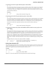
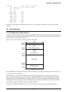
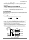
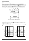
(1) Stack pointer SP1
The SP1 is used for the address data stack, and permits 16-bit data accessing.
Fig. 2.3.3.1 SP1 configuration
As shown in the figure, the D0, D1 and D10–D15 within the 16 bits are fixed at "0". 8 bits of the D2–D9
can be set by software. Furthermore, the hardware also operates for this 8-bit field. Therefore, ad-
dressing by the SP1 is done in 4-word units, and a 16-bit address data can be transferred in one
accessing. Since the SP1 performs 16-bit data accessing, this stack area is limited to the 16-bit acces-
sible RAM area even though it is within the addresses 0000H to 03FFH.
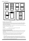
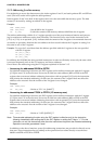
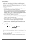
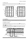
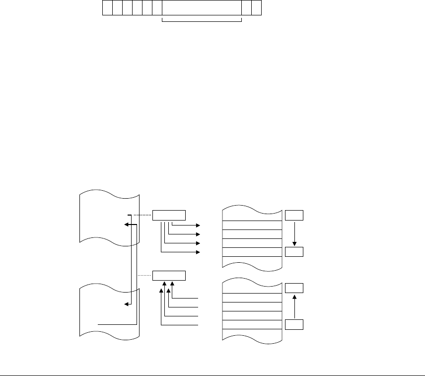
This stack is used to evacuate return addresses when the call instructions are executed or the inter-
rupts are generated. It is also used when the 16-bit data in the X or Y register is evacuated using the
PUSH instruction. The return address data is written into the stack as shown in Figure 2.3.3.2.
The SP1 is decremented after the data is evacuated and is incremented when a return instruction is
executed or after returning data by executing the POP instruction.
0SP17 00000000
Stack pointer 1
D0D1D2D9D10D15
8 bits to be modified
CALR sign8
1234H
1235H
Program memory
1235H
ROM
Address
:
:
PC
Stack (SP1)
Subroutine
:
RET
40H
SP1
00FFH
00FEH
00FDH
00FCH
ROM
Address
5H
3H
2H
1H
(= Address 100H)
(= Address FCH)
(= Address 100H)
(= Address FCH)
3FH
1235H
PC
40H
SP1
00FFH
00FEH
00FDH
00FCH
5H
3H
2H
1H
3FH
Fig. 2.3.3.2 Address stack operation