S e t t i n g U p Y o u r L i f e B o o k 6 0 0 S e r i e s
Li feBo ok 6 0 0 Series from F ujit su
9
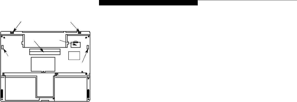
BOTTOM COMPONENTS
External Battery Locking Indentations
These indentations mate with the latches on
the external battery to provide secure mating
between the battery and your notebook.
(Figure 1-10.)
External Battery Port
This slide covered slot provides for installation
of the external battery. (Figure 1-10.)
Docking Lock Slots
These slots mate with the latch hooks of an
Enhancement Unit to lock the Enhancement
Unit and the notebook together. (Figure 1-10.)
Unit Label
This label has the model number and other
information about your notebook. In addition
the configuration portion of the label has the
serial number and manufacturer information
that you will need to give your support repre-
sentative so that he or she can help you.
It exactly identifies the version of various
components of your notebook. (Figure 1-10.)
Docking Port
This port is for connection to an Enhancement
Unit. The cover opens automatically when your
notebook is installed in an Enhancement Unit.
(Figure 1-10.)
Memory Upgrade Compartment
This compartment houses the memory upgrade
module which allows you to expand the system
memory capacity of your notebook. (See pages
115-118 for more information on installing added
memory capacity.) (Figure 1-10.)
Internal Hard Drive Compartment
This compartment contains the internal hard
drive and should only be accessed for mainte-
nance by an authorized maintenance provider.
(Figure 1-10.)
Internal Battery Compartment
This compartment houses the internal battery
and should only be opened to remove the bat-
tery for replacement or long term storage.
(Figure 1-10.)
Figure 1-10 LifeBook 600 Series Bottom
Docking
Lock Slot
Internal
Battery
Compartment
Internal
Hard Drive
Compartment
Memory
Upgrade
Compartment
Docking
Port
External
Battery Port
External Battery Locking Indentations
Docking
Lock Slot
Unit
Label


