


B-1
APPENDIX
B
Components
This Appendix describes each component making up the server.
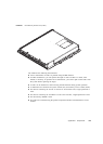
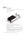
■ Section B.1, “CPU/Memory Board Unit” on page B-4
■ Section B.2, “CPU Module” on page B-6
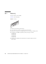
■ Section B.3, “Memory” on page B-8
■ Section B.4, “I/O Unit” on page B-9
■ Section B.5, “Hard Disk Drive” on page B-11
■ Section B.6, “PCI Cassette” on page B-12
■ Section B.7, “IOU Onboard Device Card” on page B-13
■ Section B.8, “Link Card (External I/O Expansion Unit Connection Card)” on page B-14
■ Section B.9, “Crossbar Unit” on page B-15
■ Section B.10, “Clock Control Unit” on page B-17
■ Section B.11, “XSCF Unit” on page B-17
■ Section B.12, “CD-RW/DVD-RW Drive Unit” on page B-20
■ Section B.13, “Tape Drive Unit” on page B-21
■ Section B.14, “Operator Panel” on page B-24
■ Section B.15, “Sensor Unit” on page B-26
■ Section B.16, “Power Supply Unit” on page B-27
■ Section B.17, “AC Section” on page B-28
■ Section B.18, “FAN Unit” on page B-33
■ Section B.19, “Power Cabinet” on page B-35
■ Section B.20, “Rack-mountable Dual Power Feed” on page B-37
■ Section B.21, “Backplane” on page B-38
■ Section B.22, “DDC” on page B-40
■ Section B.23, “PSU Backplane” on page B-41
■ Section B.24, “FAN Backplane” on page B-42
■ Section B.25, “Media Backplane” on page B-45
■ Section B.26, “Switch Backplane” on page B-46