


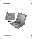
Identifying the Hardware Features
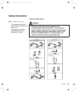
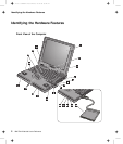
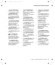
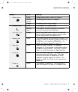
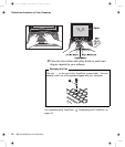
Rear View of the Computer
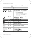
1
The security keyhole
is used with a mechanical
lock.
2
The modem
connector is used for
connecting your computer
to a telephone line.
3 The power switch turns
the computer on and off.
4 The reset switch is used
to turn the computer off if
an application hangs or if
the computer will not
accept any input. Use the
tip of a pen to press this
switch.
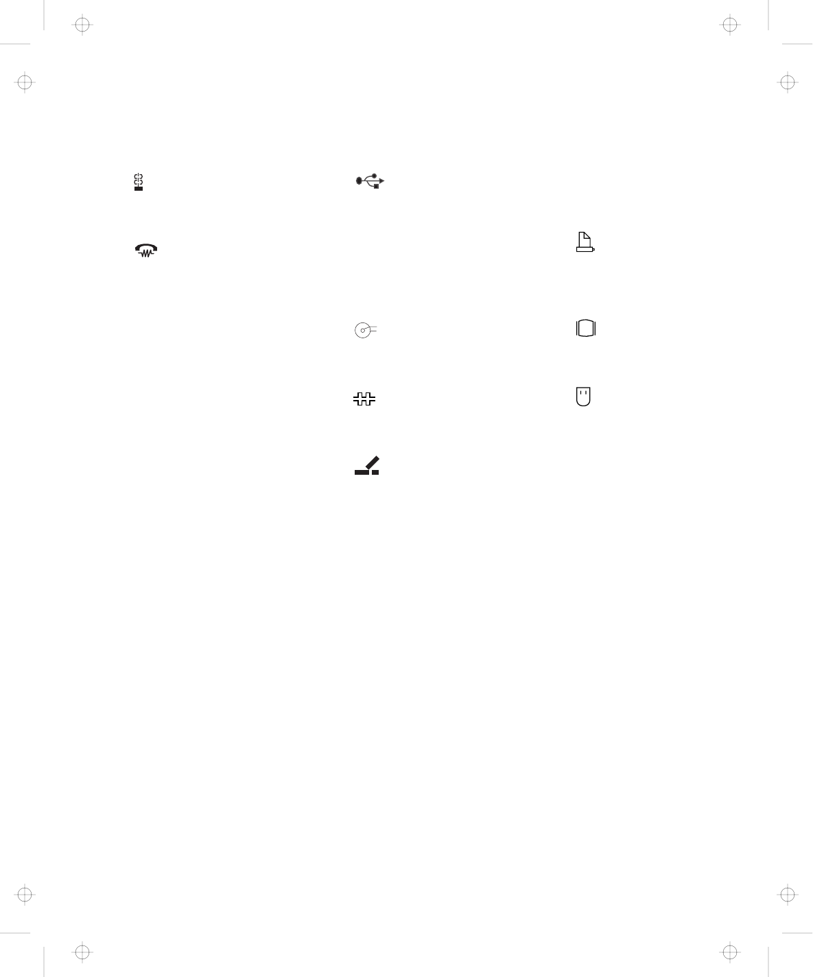
5
The universal serial
bus (USB) connector
allows you to connect any
device that conforms to this
new interface. Many
recent digital devices
comply to this new
standard.
6
-
+
The power jack is
where the AC Adapter
cable is connected.
7
The serial connector
is where you connect a
9-pin, serial-device cable.
8
The
system-expansion
connector (240-pin) allows
you to connect the port
replicator or docking
station.
9
The parallel
connector is where you
connect a parallel-printer
signal cable.
1
The external-monitor
connector is where you
attach the external monitor.
11
The
external-input-device
connector is used to
attach a mouse, external
keyboard, or external
numeric keypad to the
computer.
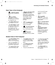
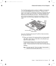
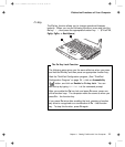
Bottom View of the Computer
1 The UltraslimBay device
lock is a lock for the
device in the UltraslimBay.
2 When the bay LED is on,
the system is in use. Do
not remove a bay device.
3 The memory-slot cover
covers the memory slot.
4 The memory slot accepts
an SDRAM dual inline
memory module (DIMM)
option.
5 The battery-pack latch
locks or releases the
battery pack.
6 Put your name plate here.
7 To remove the hard disk,
loosen this hard disk
screw. You can use the
security screw shipped with
your computer as a hard
disk screw.
8 The battery pack is a
built-in power source for
the computer.
Chapter 1. Getting Familiar with Your Computer 5
Title: C79EGMST CreationDate: 02/10/98 09:24:42