


v
4085-001
Diagnostics (Mode 2) - Input Tray Tests . . . . . . . . . . . . . . . . . . 3-27
Diagnostics (Mode 2) - Base Sensor Tests . . . . . . . . . . . . . . . . 3-29
Diagnostics (Mode 2) - Subsystem Tests . . . . . . . . . . . . . . . . . 3-31
Diagnostics (Mode 2) - Supplies Tests . . . . . . . . . . . . . . . . . . . 3-34
Diagnostics (Mode 2) - Printer Setup . . . . . . . . . . . . . . . . . . . . . 3-35
Diagnostics (Mode 2) - Error Log. . . . . . . . . . . . . . . . . . . . . . . . 3-37
Menus . . . . . . . . . . . . . . . . . . . . . . . . . . . . . . . . . . . . . . . . . . . . . . . 3-39
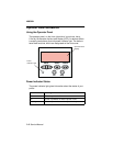
Understanding the Menu Display and Menu Buttons. . . . . . . . . 3-39
Example of Modifying a Printer Setting Using the Operator Panel . .
3-42
Operator Panel Menu Definition. . . . . . . . . . . . . . . . . . . . . . . . . 3-44
Busy/Waiting Menu Group . . . . . . . . . . . . . . . . . . . . . . . . . . . . . 3-45
Job Menu . . . . . . . . . . . . . . . . . . . . . . . . . . . . . . . . . . . . . . . . . . 3-46
Ready Menu Group . . . . . . . . . . . . . . . . . . . . . . . . . . . . . . . . . . 3-48
Configuration Menu Group. . . . . . . . . . . . . . . . . . . . . . . . . . . . . 3-60
Diagnostics Menu Group (Mode 1: Printing) . . . . . . . . . . . . . . . 3-62
Diagnostics Menu Group (Mode 2: Non-printing). . . . . . . . . . . . 3-63
Repair Information . . . . . . . . . . . . . . . . . . . . . . . . . . . . . . . . . . . . . 4-1
Handling ESD-Sensitive Parts . . . . . . . . . . . . . . . . . . . . . . . . . . . . . 4-1
Adjustments . . . . . . . . . . . . . . . . . . . . . . . . . . . . . . . . . . . . . . . . . . . 4-2
Removal Procedures . . . . . . . . . . . . . . . . . . . . . . . . . . . . . . . . . . . . 4-2
Releasing Plastic Latches . . . . . . . . . . . . . . . . . . . . . . . . . . . . . . 4-2
Rear Cover Removal . . . . . . . . . . . . . . . . . . . . . . . . . . . . . . . . . . 4-3
Operator Panel Cover/Operator Panel Removal . . . . . . . . . . . . . 4-5
Exit Tray Removal . . . . . . . . . . . . . . . . . . . . . . . . . . . . . . . . . . . . 4-5
Left Frame Cover Removal . . . . . . . . . . . . . . . . . . . . . . . . . . . . . 4-6
Left Cover Removal . . . . . . . . . . . . . . . . . . . . . . . . . . . . . . . . . . . 4-7
Right Cover/Power Switch Removal . . . . . . . . . . . . . . . . . . . . . . 4-9
Left Tray Cover Removal . . . . . . . . . . . . . . . . . . . . . . . . . . . . . . 4-11
Right Tray Cover Removal. . . . . . . . . . . . . . . . . . . . . . . . . . . . . 4-12
Ink Levels and Temperature Sensor with Bracket Removal . . . 4-13
Engine Board /Cover Removal. . . . . . . . . . . . . . . . . . . . . . . . . . 4-14
Carrier with Card Removal. . . . . . . . . . . . . . . . . . . . . . . . . . . . . 4-15
Carrier 1st Stage Drive Belt Removal . . . . . . . . . . . . . . . . . . . . 4-17
Carrier Printhead Latch Removal. . . . . . . . . . . . . . . . . . . . . . . . 4-17
Multi-Purpose Feeder (MPF) Motor and Sensor Removal. . . . . 4-17
Power Supply Removal . . . . . . . . . . . . . . . . . . . . . . . . . . . . . . . 4-19
Pump Housing/Maintenance Station/Ink Waste Tank/Transport Car-
rier Motor Removal. . . . . . . . . . . . . . . . . . . . . . . . . . . . . . . . . . . 4-20
Index Card Assembly Removal . . . . . . . . . . . . . . . . . . . . . . . . . 4-22
Cover-Open Sensor Removal . . . . . . . . . . . . . . . . . . . . . . . . . . 4-23
RIP-EMC Shield Assembly/RIP Card Removal . . . . . . . . . . . . . 4-24