Installing
Release 3.3 161
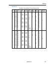
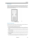
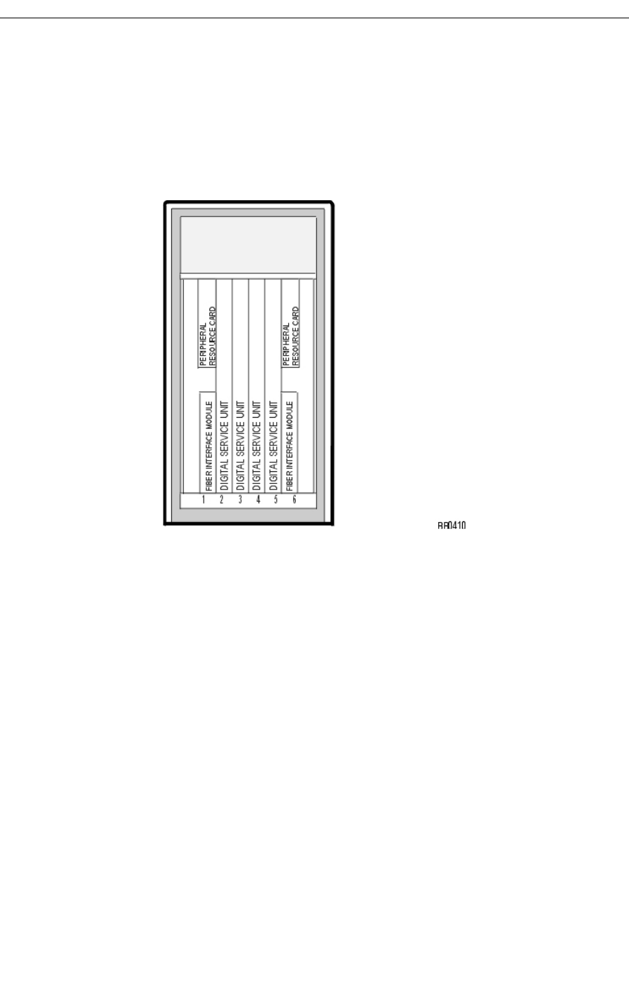
DSU Card Layout
Each DSU node has one or two FIMs, depending on the number and location of DSU cards
installed in the node. The FIM in the bottom of slot 1 provides communications with the 3300
Controller for the DSU cards in slots 2 and 3, and the FIM in the bottom of slot 6 provides
communications for the DSU cards in slots 4 and 5. You must install and cable the FIMs before
you install any cards in the DSU node.
DSU Card Layout
Connect Fiber Cable to the DSU
The fiber optic cable connects the FIMs in the 3300 Controller to the FIMs in the DSU node.
To connect the fiber optic cable to the FIM in the peripheral node:
1. Review the guidelines for handling fiber optic cable.
2. Route the fiber optic cable through the sliding cable port at the rear of the DSU cabinet
into the cabinet. Extend the fiber cable approximately 30 cm (1 ft) beyond the front of the
cabinet.
3. Install a short piece of nylon spiral wrap over the cable at the point where the cable exits
the rear of the cabinet.
4. Close the sliding cable port door. Ensure that the door closes on the nylon spiral-wrapped
section of fiber cable.
5. Remove the plastic dust caps from the fiber optic cable and the connector ferrules on the
FIM faceplate.
6. Plug the fiber connectors into the connectors on the FIM faceplate. The fiber connectors
have a small key that must be aligned with a slot on the FIM connectors. Lock each


