


3300 ICP Hardware User Guide
218 Release 3.3
3. Go to the rear of the cabinet.
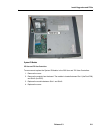
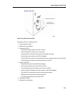
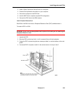
4. Disconnect the Ethernet LAN cables from the dual 10Base-T connector assembly. The
dual 10Base-T connector assembly is located in the 12th FIM slot.
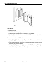
5. Remove and retain the two screws that fasten the dual 10Base-T connector assembly to
the fiber carrier box.
6. Remove the dual 10Base-T connector assembly and carefully draw the attached cables
out through the 12th FIM slot. If the cables become entangled, do not attempt to force
them from the cabinet. Reach in through the front of the cabinet and free the cables.
7. Unpack the replacement 10Base-T connector assembly.
8. Insert the cables that are attached to the replacement 10Base-T connector assembly into
the 12th FIM slot.
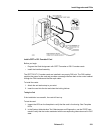
9. Go to the front of the cabinet and carefully draw the two cables through to the front of the
cabinet. Route the cables along the base of the cabinet.
10. At the rear of the cabinet insert the dual 10Base-T connector assembly into the 12th FIM
slot.
11. Fasten the dual 10Base-T connector assembly to the fiber carrier using the two screws
that you removed in step 5.
12. Connect the two Ethernet cables to the 8-position, 8-pin connectors on the dual 10Base-T
connector assembly.
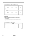
13. At the front of the cabinet, connect the 10 Base-T internal cable for plane A to port J5 on
the faceplate of the Ethernet interface card in slot 1/1/3.
14. Connect the 10 Base-T internal cable for plane B to port J5 on the faceplate of the Ethernet
interface card in slot 1/1/6.
15. Reset the ETI cards using the RESET switch on the faceplate of each ETI card. The RDY
LED on the ETI cards turn on steady indicating that the ETI cards are receiving their
software loads from OPS Manager.
DSU FRUs
Power Down the DSU
1. To power down a DSU node:
2. Set the power switch on the rear of the node to ‘0’ (OFF).
3. Unplug the external power cord at the rear of the node.
Power Up the DSU
To power up a DSU node:
1. Connect the external power cord at the rear of the node.
2. Set the power switch on the rear of the node to ‘I’ (ON).