


Specifications
Release 3.3 77
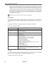
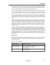
The trunk circuits on the LS/GS trunk card are configured during the initial system programming
process. Each trunk circuit can be programmed to operate in an LS or GS mode. LS or GS
options can be changed at any time via the System Administration Tool.
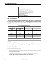
When GS mode is selected, incoming trunk calls are initiated by a ground on the Tip lead, or
by a ringing source applied to the trunk by the CO. Outgoing calls are initiated by seizing an
idle trunk (via the DATA IN link of the trunk circuit) and by placing a ground on the Ring lead.
When LS mode is selected, incoming trunk calls are initiated by a ringing source applied to the
trunk by the CO. Outgoing calls are initiated by first seizing an idle trunk (via the DATA IN link
on an LS/GS trunk card circuit) and by placing a low resistance loop across the Tip and Ring
leads.
Dictation equipment used on a trunk can indicate a busy or idle status by interconnecting a
third wire lead to either the T(MR) or R(MR) termination at the 3300 ICP system. The actual
configuration that should be used is dependent upon the type of centralized dictation equipment
used and its busy status (i.e., whether a busy condition is indicated by a voltage or ground
condition on the third wire; see Dictation Access in Troubleshooting, Hardware, Peripheral Unit,
LS/GS Trunk Card).
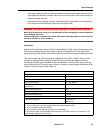
In addition, T(MR) and R(MR) leads can be connected to the CO for message registration
purposes. The system can record message registration pulses either by polarity reversal over
the Tip and Ring leads (when the called party answers) or by loop signaling from the CO over
the second pair of leads. Various types of terminations can be used for message registration
pulses transmitted from the CO. In each case, M and MM leads terminate respectively on the
T(MR) and R(MR) leads. A message registration signal is given when the MR contact at the
CO is closed.
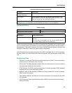
E & M Trunk Card
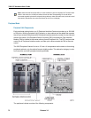
The E&M Trunk card provides a means of interfacing four external trunk circuits to the system.
E&M trunk cards connect to any Peripheral Interface card slot on the peripheral shelf via
connectors J1 and J2.
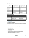
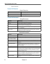
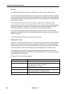
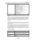
E&M Trunk Card Specifications
Variants Available: A-law (UK), µ-law (NA)
Number of Circuits per Card: 4 E&M trunk circuits
Power Consumption: Type I, mechanical CO: 21.45 watts
Type I, electronic CO: 8.01 watts
Type V: 4.83 watt
External Loop Resistance: Type I: 150 ohms
Type V: 4000 ohms