Specifications
Release 3.3 73
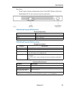
• Peripheral Interface Cards: The Peripheral Interface cards connect telephone trunks and
peripheral devices (such as SUPERSET™ telephones) to the system. They are located
in slots 1 through 12.
• Power Converter (AC): The AC power converter converts AC input power to the voltages
required by the circuit cards and FIMs (+5 Vdc, +12 Vdc, -27 Vdc, -48 Vdc and 80 Vac
ringing). It is installed in slots 13 to 15.
• Peripheral Switch Controller card (PSC): The PSC card performs all peripheral switch
functions for up to 12 Peripheral Interface cards (or 24 cards with the addition of a peripheral
slave cabinet. It is installed in slot 16 of the master peripheral cabinet.
• Fiber Interface Module (FIM): The FIM connects the peripheral node to the control node.
It is installed in slot 17 of the master peripheral cabinet.
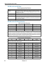
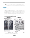
• Cabinet Frame: Each peripheral cabinet has 17 slots numbered from left to right. Slots 1
to 12 support Peripheral Interface cards and slots 13 to 15 hold the Power Converter. A
master peripheral cabinet also holds a PSC card in slot 16, a FIM in slot 17, and a Peripheral
Interconnect card in slot 16B (if your unit is expanded). A peripheral slave cabinet holds
a Peripheral Interconnect card in slot 16, in addition to the Peripheral Interface cards and
Power Converter. Slots 16B and 17 of the slave cabinet are not programmable.
• Power Distribution Unit (PDU) (AC): The AC PDU filters and switches the 120/240 Vac
input power to the Power Converter and fan assembly.
• Power Distribution Unit (PDU) (DC): The DC PDU filters and switches the -48 Vdc input
power to the Power Converter and fan assembly. Note that the server is available in AC
version only.
• Fan Assembly: Two fans in the removable fan assembly cool the cabinet.
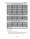
• Rear Panel: The following switches and connectors are located on the rear panel of the
cabinet:
- A power on/off switch
- A fuse to protect the line lead on the input power (AC systems) or circuit breaker (DC
systems)
- A 3-conductor male receptacle to connect AC input power
- A sliding door for the Tx and Rx fiber optic cables
- An RS-232 Maintenance Terminal port for remote access (remote maintenance con-
nections will only work on the master cabinet of a peripheral pair)
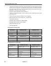
- Nine 25-pair male, filtered, Amphenol connectors are located on the rear panel. All
lines and trunks from the main distribution frame connect to the eight horizontally
positioned connectors using 25-pair cable. The single vertically positioned 25-pair
D-phone connector provides power and contact closure to an optional external system
fail transfer unit.
- A 3-conductor female plug is recessed in the rear panel behind a small cover plate
(AC systems only). The plug connects to the power connector on the AC Power
converter.
Note: 3300 peripheral cabinets with a slightly smaller frame are available for stacking in a 19" rack.


