


3300 ICP Hardware User Guide
78 Release 3.3
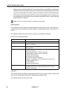
E&M Trunk Card Settings
The E&M trunk card accommodates E&M interface circuits Types I through V. The configuration
of the four trunk circuits on the E&M trunk card to accommodate these five interface types is
accomplished by using DIP switches SN-1 and SN-2. These DIP switches must be set on-site
as follows:
Operation
In addition to the E&M trunk types that can be configured by using DIP switches, it is also
possible to configure various software options via system programming. The software options
can be changed at any time using the System Administration Tool.
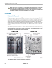
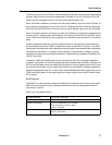
Fiber Interface Module (FIM)
Guidelines for Handling Fiber Optic Cable
• Never touch the tip of a fiber connector. Cleanliness of the connector ferrule (tip) is impor-
tant for error free transmission.
• Always place the dust caps onto the connectors immediately after disconnecting.
• You can clean the ferrule tips on the connectors with ethyl-alcohol.
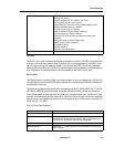
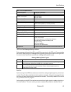
Features Provided: 2-wire/4-wire conversion
A-D/D-A conversion
E&M signaling leads
2 dB software-switchable VNL pads
software-selectable standard carrier levels
switch-selectable 2-wire or 4-wire operation
protection/isolation against foreign potentials
switch-selectable E&M types
self-test capability
automatic card identification
Compliance: Complies with all pertinent sections EIA Standard RS-464.
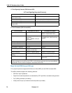
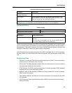
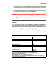
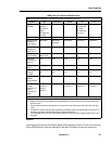
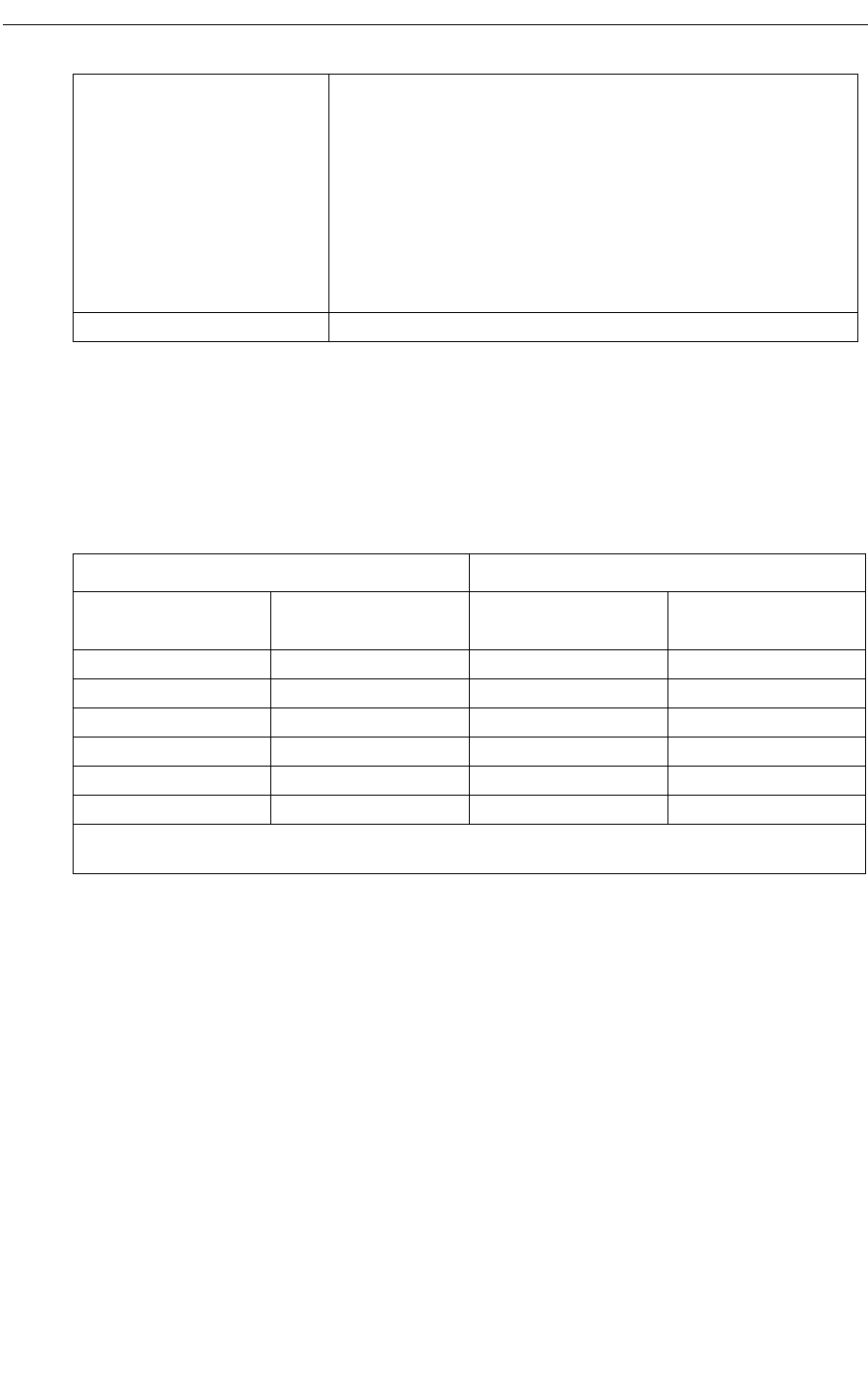
SN-1 and SN-2 Switch Settings
Types of Interface Cards Switch Positions
Signal/carrier set
types
Co-located trunk
types
SN-1 SN-2
TYPE I NONE A B
TYPE II TYPE II B A
TYPE IV TYPE IV B A
TYPE V TYPE I B B
TYPE V TYPE III B B
TYPE V TYPE V B B
Note: Positions are SN-1 and SN-2 where N is the particular trunk circuit number on the card (1
through 4).