


113
CHAPTER 3 SPECIFICATIONS
3
3.4 Buffer Memory Assignment
3.4.2 Details of the buffer memory
(21)CH Sensor correction value setting (Un\G45, Un\G77, Un\G109, Un\G141)
Set the correction value when measured temperature and actual temperature are different.
For details on the sensor correction function, refer to the following.
Page 209, Section 4.14
(a) Setting range
Set the value within the range -5000 to 5000 (-50.00% to 50.00%) of the full scale of the set input range.
( Page 96, Section 3.4.2 (12))
(b) Enablement of setting contents
When Normal sensor correction (one-point correction) (0
H
) is set in Sensor correction function selection
(Un\G785), the setting content is enabled. ( Page 159, Section 3.4.2 (87))
(c) Default value
The default values are set to 0 (0.00%) in all channels.
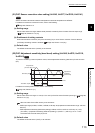
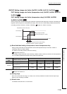
(22)CH Adjustment sensitivity (dead band) setting (Un\G46, Un\G78, Un\G110,
Un\G142)
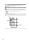
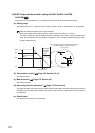
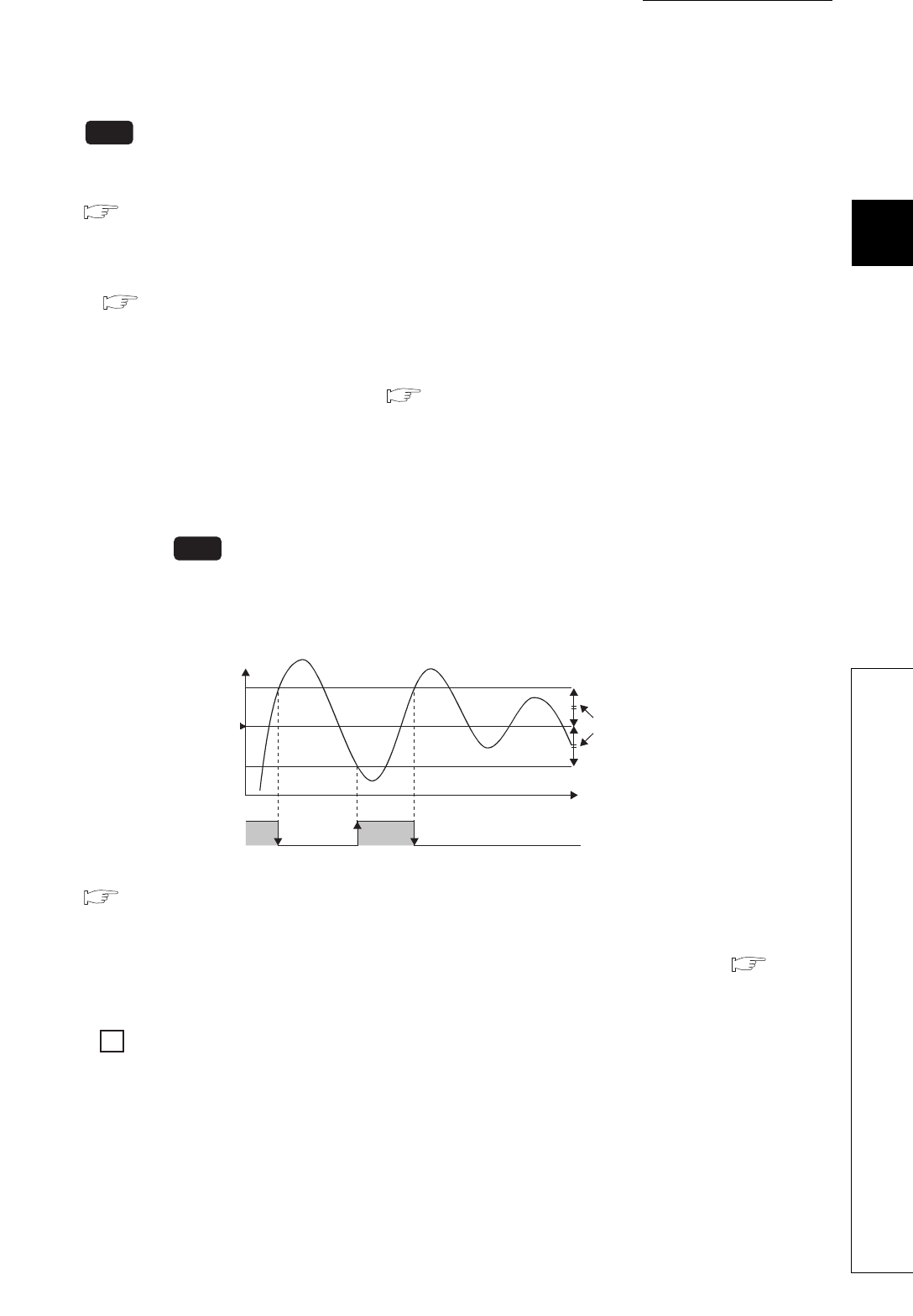
To prevent a chattering in the two-position control, set the adjustment sensitivity (dead band) for the set value
(SV).
For details on the two-position control, refer to the following.
Page 166, Section 4.3 (1)
(a) Setting range
Set the value within the range 1 to 100 (0.1% to 10.0%) of the full scale of the set input range. ( Page 96,
Section 3.4.2 (12))
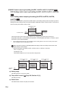
Ex.
When the value of the buffer memory is set as follows
•CH Input range (Un\G32, Un\G64, Un\G96, Un\G128): 38 (temperature measurement range: -200.0 to
400.0°C)
•CH Adjustment sensitivity (dead band) setting (Un\G46, Un\G78, Un\G110, Un\G142): 10 (1.0%)
(Full scale) × (Adjustment sensitivity (dead band) setting) = (400.0°C - (-200.0°C)) × 0.01 = 6.0°C
The dead band is the set value (SV) 6.0°C.
(b) Default value
The default values are set to 5 (0.5%) in all channels.
Common
Common
Temperature
process value (PV)
ON
OFF
Set value (SV)
Transistor output
Time
Adjustment
sensitivity
(dead band)