


159
CHAPTER 3 SPECIFICATIONS
3
3.4 Buffer Memory Assignment
3.4.2 Details of the buffer memory
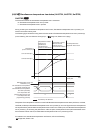
(87)Sensor correction function selection (Un\G785)
Select the method of the sensor correction for each channel.
For details on the sensor correction function, refer to the following.
Page 209, Section 4.14
(a) Setting range
•0
H
: Normal sensor correction (one-point correction)
•1
H
: Sensor two-point correction
(b) Enablement of setting contents
Enable the setting contents by turning Setting change instruction (YnB) OFF ON OFF during the setting
mode (Setting/operation mode status (Xn1): OFF).
(c) Default value
Default value is set to Normal sensor correction (one-point correction) (0
H
).
(88)Temperature conversion completion flag (Un\G786)
This flag checks whether the temperature conversion has started properly for each channel. The following values
are stored in this buffer memory area.
•0
H
: During conversion or unused CH
•1
H
: First temperature conversion completed
This flag becomes During conversion or unused CH (0
H
) during temperature conversion or for unused channels.
When the first temperature conversion is completed and the temperature process value (PV) is stored in the
buffer memory, First temperature conversion completed (1
H
) is set.
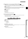
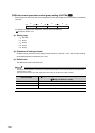
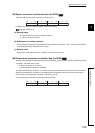
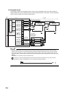
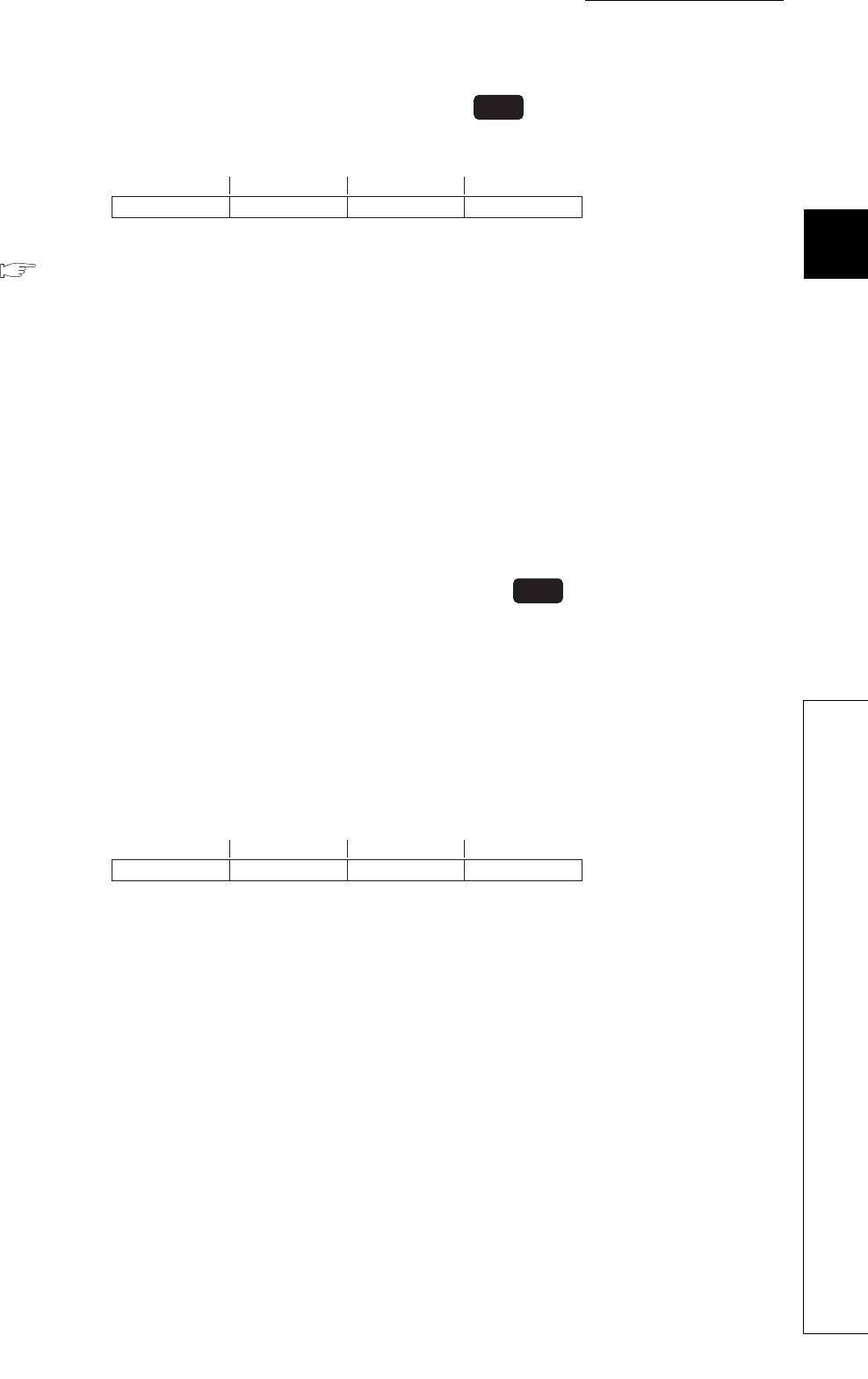
The following figure shows the channel assignment of this area.
Common
b15 b0
to to to to
b8 b7 b4 b3b11b12
CH4 CH3 CH2 CH1
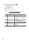
Common
b15 b0
to to to to
b8 b7 b4 b3b11b12
CH4 CH3 CH2 CH1