


156
(84)CH Simultaneous temperature rise status (Un\G734, Un\G750, Un\G766,
Un\G782)
The execution state of the simultaneous temperature rise is monitored.
• 0: Simultaneous temperature rise not in process
• 1: Simultaneous temperature rise in process
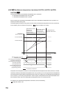
During control by the simultaneous temperature rise function, Simultaneous temperature rise in process (1) is
stored in this buffer memory area.
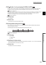
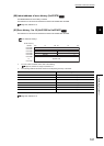
The following figure shows the timing when the value is set to Simultaneous temperature rise not in process (0).
(In the following, CH1 and CH2 are set to group 1. ( Page 154, Section 3.4.2 (80)))
Completion of the temperature rise does not set CH Simultaneous temperature rise status (Un\G734, Un\G750,
Un\G766, Un\G782) to Simultaneous temperature rise not in process (0). As in the figure above, the temperature
rise is performed by the simultaneous temperature rise function to a certain point, and Simultaneous temperature
rise in process (1) is set during the performance. After the point, the temperature rise is performed based on the
PID constants of each channel, and Simultaneous temperature rise not in process (0) is set.
For details on the simultaneous temperature rise function, refer to the following.
Page 238, Section 4.20
Standard
CH1 Set value (SV)
The temperature rise
completion times match.
Temperature is raised
based on the PID
constants of each
channel for this interval.
Temperature is raised
based on the
simultaneous
temperature rise
function for this interval.
Temperature
process value (PV)
Time
CH2 Set value (SV)
Temperature rise start
1
1
00
0
Group 1
arrival point
CH1 Simultaneous temperature
rise status (Un\G734) and
CH2 Simultaneous temperature
rise status (Un\G750)
CH1 Temperature rise
judgment flag (Un\G17) and
CH2 Temperature rise
judgment flag (Un\G18)
Setting/operation mode
instruction (Yn1)
ON
OFF
Executed by the Q64TCN