


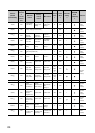
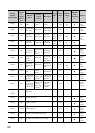
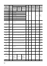
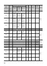
72
288(120
H
)
CT1
CT ratio setting
*11
800 R/W ×
Page 141,
Section
3.4.2 (57)
289(121
H
)
CT2
CT ratio setting
*11
290(122
H
)
CT3
CT ratio setting
*11
291(123
H
)
CT4
CT ratio setting
*11
292(124
H
)
CT5
CT ratio setting
*11
293(125
H
)
CT6
CT ratio setting
*11
294(126
H
)
CT7
CT ratio setting
*11
295(127
H
)
CT8
CT ratio setting
*11
296(128
H
)
System area to
543(21F
H
)
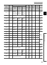
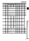
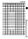
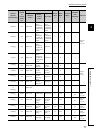
544(220
H
)
CH1
Sensor two-point correction offset value (measured
value)
*9
0R/W
Page 142,
Section
3.4.2 (58)
545(221
H
)
CH1
Sensor two-point correction offset value (corrected
value)
*9
0R/W
Page 142,
Section
3.4.2 (59)
546(222
H
)
CH1
Sensor two-point correction gain value (measured
value)
*9
0R/W
Page 143,
Section
3.4.2 (60)
547(223
H
)
CH1
Sensor two-point correction gain value (corrected
value)
*9
0R/W
Page 143,
Section
3.4.2 (61)
548(224
H
)
CH1
Sensor two-point correction offset latch request
*9
0R/W × ×
Page 144,
Section
3.4.2 (62)
549(225
H
)
CH1 Sensor two-point correction offset latch completion 0 R × ×
Page 144,
Section
3.4.2 (63)
550(226
H
)
CH1
Sensor two-point correction gain latch request
*9
0R/W × ×
Page 144,
Section
3.4.2 (64)
551(227
H
)
CH1 Sensor two-point correction gain latch completion 0 R × ×
Page 145,
Section
3.4.2 (65)
552(228
H
)
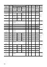
System area to
563(233
H
)
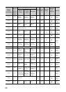
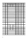
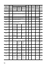
564(234
H
)
CH1
Setting change rate limiter (temperature drop)
*12
0R/W ×
Page 119,
Section
3.4.2 (28)
565(235
H
)
System area to
570(23A
H
)
571(23B
H
)
All CHs
During AT loop
disconnection
detection
function
enable/disable
setting
System area
During AT loop
disconnection
detection
function
enable/disable
setting
0R/W ×
Page 145,
Section
3.4.2 (66)
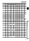
572(23C
H
)
System area
Address
(decimal
(hexadecimal))
Target
channel
or
current
sensor
(CT)
Setting contents
Default
value
*1
Read/
Write
*2
Automatic
setting
*3
E
2
PROM
write
availability
*4
Reference
Standard
control
Heating-
cooling
control
Mix control