


62
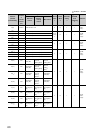
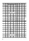
42(2A
H
)
CH1
Upper limit
output limiter
Heating upper
limit output
limiter
Heating upper
limit output
limiter
1000 R/W ×
Page 110,
Section
3.4.2 (19)
43(2B
H
)
CH1
Lower limit
output limiter
System area System area 0 R/W ×
44(2C
H
)
CH1 Output variation limiter setting 0 R/W ×
Page 112,
Section
3.4.2 (20)
45(2D
H
)
CH1 Sensor correction value setting 0 R/W ×
Page 113,
Section
3.4.2 (21)
46(2E
H
)
CH1 Adjustment sensitivity (dead band) setting 5 R/W ×
Page 113,
Section
3.4.2 (22)
47(2F
H
)
CH1
Control output
cycle setting
Heating control
output cycle
setting
Heating control
output cycle
setting
30 R/W ×
Page 114,
Section
3.4.2 (23)
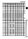
48(30
H
)
CH1 Primary delay digital filter setting 0 R/W ×
Page 115,
Section
3.4.2 (24)
49(31
H
)
CH1 Control response parameters 0 R/W ×
Page 116,
Section
3.4.2 (25)
50(32
H
)
CH1 AUTO/MAN mode shift 0 R/W ×
Page 117,
Section
3.4.2 (26)
51(33
H
)
CH1 MAN output setting 0 R/W ×
Page 118,
Section
3.4.2 (27)
52(34
H
)
CH1
Setting change rate limiter/Setting change rate
limiter (temperature rise)
*10
0R/W ×
Page 119,
Section
3.4.2 (28)
53(35
H
)
CH1 AT bias 0 R/W
Page 120,
Section
3.4.2 (29)
54(36
H
)
CH1
Forward/reverse
action setting
System area System area 1 R/W ×
Page 121,
Section
3.4.2 (30)
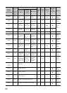
55(37
H
)
CH1 Upper limit setting limiter
1300
(TT)
6000
(RT)
*5
R/W
Page 122,
Section
3.4.2 (31)
56(38
H
)
CH1 Lower limit setting limiter
0(TT)
-2000
(RT)
*5
R/W
57(39
H
)
CH1 System area
58(3A
H
)
CH1
Heater disconnection alert setting
*11
0R/W ×
Page 123,
Section
3.4.2 (32)
59(3B
H
)
CH1
Loop
disconnection
detection
judgment time
System area System area 480 R/W ×
Page 124,
Section
3.4.2 (33)
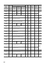
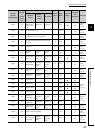
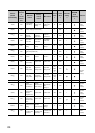
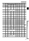
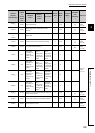
Address
(decimal
(hexadecimal))
Target
channel
or
current
sensor
(CT)
Setting contents
Default
value
*1
Read/
Write
*2
Automatic
setting
*3
E
2
PROM
write
availability
*4
Reference
Standard
control
Heating-
cooling
control
Mix control