


85
CHAPTER 3 SPECIFICATIONS
3
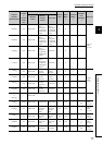
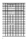
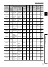
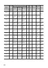
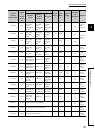
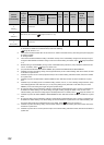
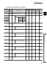
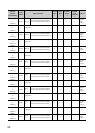
3.4 Buffer Memory Assignment
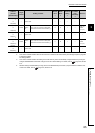
3.4.1 Q64TCN buffer memory assignment list
*1 This default value is set after the module is turned off and on or after the CPU module is reset and the reset is cancelled.
*2 This column indicates whether data can be read from or written to the buffer memory area through sequence programs.
R: Reading enabled
W: Writing enabled
*3 This column indicates whether the setting in the buffer memory area is automatically changed when the input range is
changed. Enable/disable of automatic change can be set on Switch Setting. For details, refer to Page 220, Section
4.15.
*4 Whether writing to the E
2
PROM by turning off and on E
2
PROM backup instruction (Yn8) is enabled is indicated in this
column. For details, refer to Page 270, Section 4.30
1389(56D
H
)
System area to
1391(56F
H
)
1392(570
H
)
All CHs
History
15
Error code, error occurrence time (Data
structure is the same as that of History 1.)
0R × ×
Page 161,
Section
3.4.2 (91)
to
1396(574
H
)
1397(575
H
)
System area to
1399(577
H
)
1400(578
H
)
All CHs
History
16
Error code, error occurrence time (Data
structure is the same as that of History 1.)
0R × ×
Page 161,
Section
3.4.2 (91)
to
1404(57C
H
)
1405(57D
H
)
System area to
4095(FFF
H
)
Address
(decimal
(hexadecimal))
Target
channel
Setting contents
Default
value
*1
Read/
Write
*2
Automatic
setting
*3
E
2
PROM
write
availability
*4
Reference