


81
CHAPTER 3 SPECIFICATIONS
3
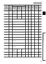
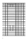
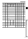
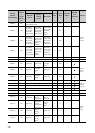
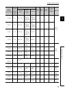
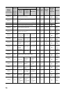
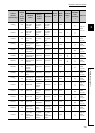
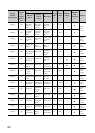
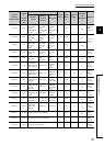
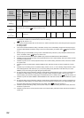
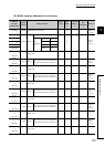
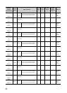
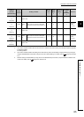
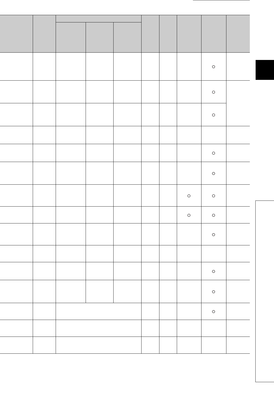
3.4 Buffer Memory Assignment
3.4.1 Q64TCN buffer memory assignment list
773(305
H
)
CH4
Process value
(PV) scaling
function
enable/disable
setting
*9
Process value
(PV) scaling
function
enable/disable
setting
*6*9
Process value
(PV) scaling
function
enable/disable
setting
*9
0R/W ×
Page 152,
Section
3.4.2 (76)
774(306
H
)
CH4
Process value
(PV) scaling
lower limit
value
*9
Process value
(PV) scaling
lower limit
value
*6*9
Process value
(PV) scaling
lower limit
value
*9
0R/W ×
Page 153,
Section
3.4.2 (77)
775(307
H
)
CH4
Process value
(PV) scaling
upper limit
value
*9
Process value
(PV) scaling
upper limit
value
*6*9
Process value
(PV) scaling
upper limit
value
*9
0R/W ×
776(308
H
)
CH4
Process value
(PV) scaling
value
Process value
(PV) scaling
value
*6
Process value
(PV) scaling
value
0R × ×
Page 153,
Section
3.4.2 (78)
777(309
H
)
CH4
Derivative action
selection
*9
Derivative
action
selection
*6*9
Derivative
action
selection
*9
0R/W ×
Page 153,
Section
3.4.2 (79)
778(30A
H
)
CH4
Simultaneous
temperature rise
group setting
*9
System area
Simultaneous
temperature
rise group
setting
*9
0R/W ×
Page 154,
Section
3.4.2 (80)
779(30B
H
)
CH4
Simultaneous
temperature rise
gradient data
System area
Simultaneous
temperature
rise gradient
data
0R/W
Page 154,
Section
3.4.2 (81)
780(30C
H
)
CH4
Simultaneous
temperature rise
dead time
System area
Simultaneous
temperature
rise dead time
0R/W
Page 155,
Section
3.4.2 (82)
781(30D
H
)
CH4
Simultaneous
temperature rise
AT mode
selection
System area
Simultaneous
temperature
rise AT mode
selection
0R/W ×
Page 155,
Section
3.4.2 (83)
782(30E
H
)
CH4
Simultaneous
temperature rise
status
System area
Simultaneous
temperature
rise status
0R × ×
Page 156,
Section
3.4.2 (84)
783(30F
H
)
CH4
Setting change
rate limiter unit
time setting
*9
Setting change
rate limiter unit
time setting
*6*9
Setting change
rate limiter unit
time setting
*9
0R/W ×
Page 157,
Section
3.4.2 (85)
784(310
H
)
All CHs
Peak current
suppression
control group
setting
*9
System area System area 0 R/W ×
Page 158,
Section
3.4.2 (86)
785(311
H
)
All CHs
Sensor correction function selection
*9
0R/W ×
Page 159,
Section
3.4.2 (87)
786(312
H
)
All CHs Temperature conversion completion flag 0 R × ×
Page 159,
Section
3.4.2 (88)
787(313
H
)
All CHs Function extension bit monitor 0 R × ×
Page 160,
Section
3.4.2 (89)
Address
(decimal
(hexadecimal))
Target
channel
or
current
sensor
(CT)
Setting contents
Default
value
*1
Read/
Write
*2
Automatic
setting
*3
E
2
PROM
write
availability
*4
Reference
Standard
control
Heating-
cooling
control
Mix control