


330
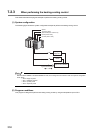
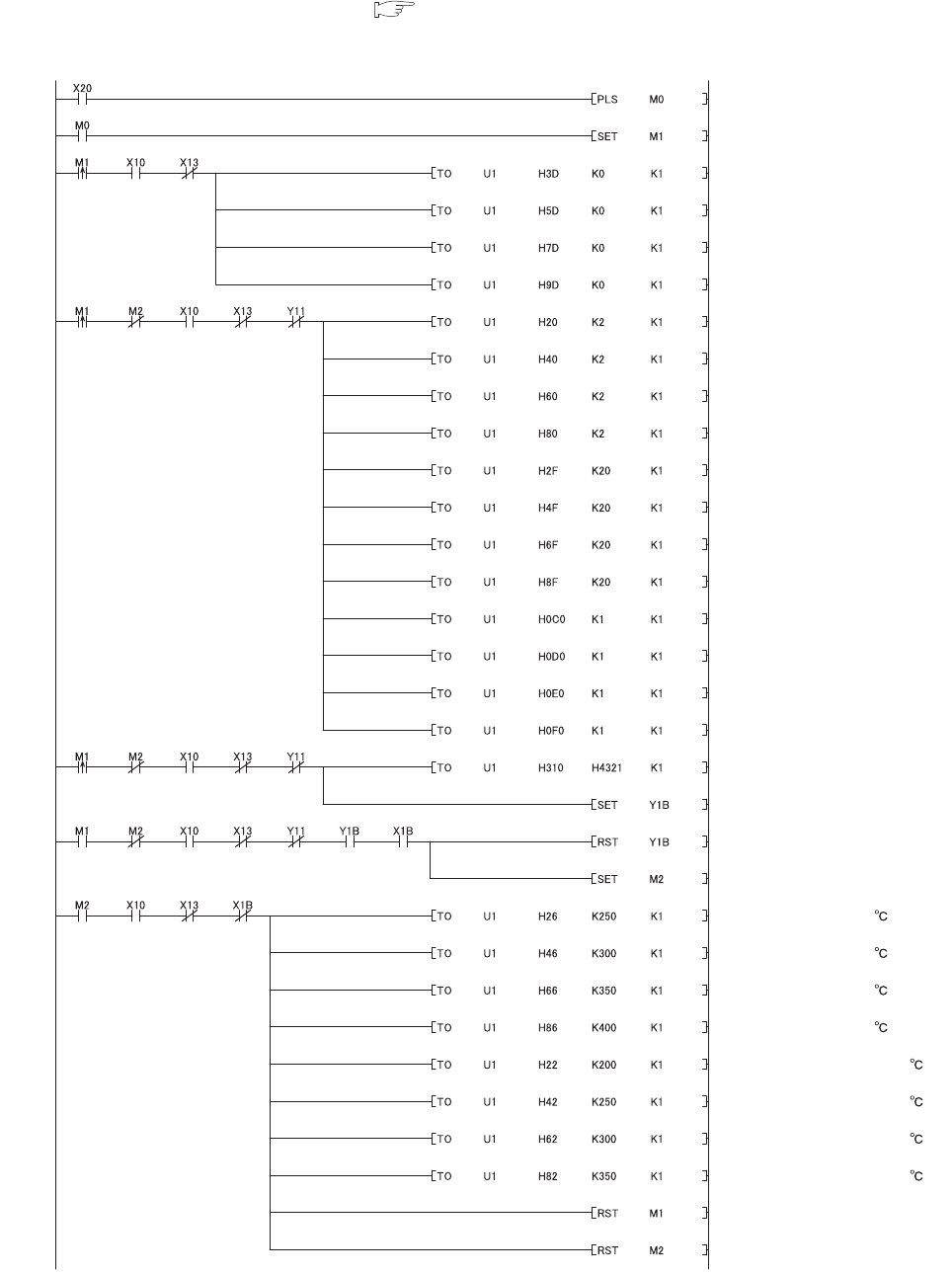
(b) Program example where the peak current suppression function is used
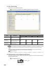
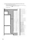
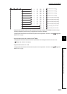
• Program that changes the setting/operation mode
This program is the same as that of when the module is in the standard control (such as auto tuning, self-
tuning, and error code read). ( Page 315, Section 7.2.1 (6) (f))
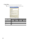
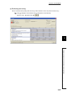
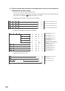
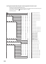
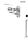
• Initial setting program
Flag 0 for setting value write: ON
Flag 1 for setting value write: ON
CH1 Unused channel setting: Used
CH2 Unused channel setting: Used
CH3 Unused channel setting: Used
CH4 Unused channel setting: Used
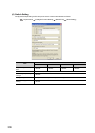
CH1 Input range: 2
CH2 Input range: 2
CH3 Input range: 2
CH4 Input range: 2
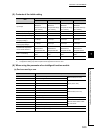
CH1 Control output cycle setting: 20s
CH2 Control output cycle setting: 20s
CH3 Control output cycle setting: 20s
CH4 Control output cycle setting: 20s
CH1 Alert 1 mode setting
: Upper limit input alert
CH2 Alert 1 mode setting
: Upper limit input alert
CH3 Alert 1 mode setting
: Upper limit input alert
CH4 Alert 1 mode setting
: Upper limit input alert
Peak current suppression control
group setting:
CH1: Group 1, CH2: Group 2
CH3: Group 3, CH4: Group 4
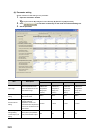
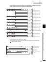
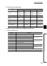
Setting change instruction: ON
Setting change instruction: OFF
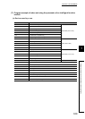
CH1 Alert set value 1: 250
CH2 Alert set value 1: 300
CH3 Alert set value 1: 350
CH4 Alert set value 1: 400
CH1 Set value (SV) setting: 200
CH2 Set value (SV) setting: 250
CH3 Set value (SV) setting: 300
CH4 Set value (SV) setting: 350
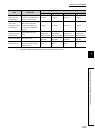
Flag 1 for setting value write: OFF
Flag 2 for setting value write: OFF
Flag 2 for setting value write: ON