


260
(2) Dead band
Dead band refers to the temperature area where neither heating control output nor cooling control output is
performed. When the temperature process value (PV) is stable within this area, output is not performed for the
slight change in the temperature, resulting in energy saving.
Ex.
When buffer memory values are set as following:
•CH Input range (Un\G32, Un\G64, Un\G96, Un\G128): 38 (temperature measurement range: -200.0°C to
400.0°C)
•CH Set value (SV) setting (Un\G34, Un\G66, Un\G98, Un\G130): 2000 (200.0°C)
•CH Overlap/dead band setting (Un\G723, Un\G739, Un\G755, Un\G771): 25 (2.5%)
200.0°C to 215.0°C is the area for dead band.
(Full scale) × (Overlap setting) = (400.0°C - (-200.0°C)) × 0.025 = 15.0°C
The temperature where cooling operation starts = (Set value (SV)) + 15.0°C = 215.0°C
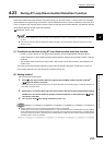
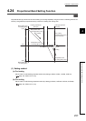
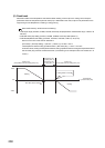
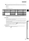
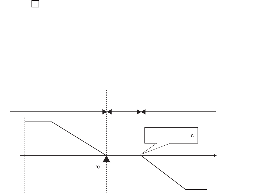
As shown below, shifting the temperature where cooling operation starts to the higher temperature side of
the set value (SV) produces a dead band area. (The following is an example of when the module is in P
control.)
Heating only
(manipulated value for cooling (MVc): 0%)
Cooling only
(manipulated value for heating (MVh): 0%)
Heating
Set value (SV) is 200.0 .
Cooling
Temperature
process value (PV)
Cooling starts at 215.0 .
100%
0%
-100%
Manipulated value
for heating (MVh): 0%
Manipulated value
for cooling (MVc): 0%