


170
(6) Condition to perform PID control
The condition to be able to perform PID control
*1
depends on the settings of the followings.
• Setting/operation mode instruction (Yn1) ( Page 56, Section 3.3.3 (1))
• PID continuation flag (Un\G169)) ( Page 131, Section 3.4.2 (43))
•CH PID control forced stop instruction (YnC to YnF) ( Page 58, Section 3.3.3 (7))
•CH Stop mode setting (Un\G33, Un\G65, Un\G97, Un\G129) ( Page 103, Section 3.4.2 (13))
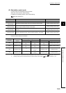
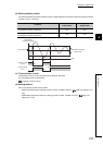
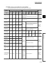
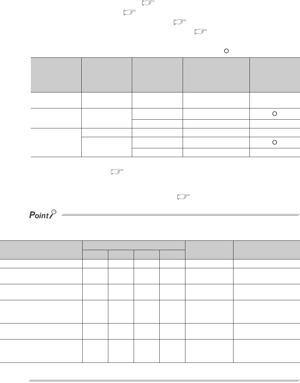
The following table shows the relationship between the status of PID control
*1
and each of the settings above.
: Performed ×: Not performed
*1 Here, this is the generic term for two-position control, P control, PI control, PD control, and PID control.
*2 For the timing of each, refer to Page 50, Section 3.3.2 (2).
Even though the conditions above are met, PID control is not performed when CH Unused channel setting
(Un\G61, Un\G93, Un\G125, Un\G157) is set to Unused (1). ( Page 126, Section 3.4.2 (35))
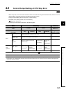
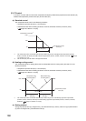
The manipulated value (MV) and manipulated value (MV) for output with another analog module of when CH PID control
forced stop instruction (YnC to YnF) is turned on from off are as follows.
When CH PID control forced stop instruction (YnC to YnF) is turned off from on, the forced stop of PID control is released.
After the release, PID operation starts from the beginning.
Setting/operation
mode instruction
(Yn1)
*2
PID continuation
flag (Un\G169)
CH PID control
forced stop
instruction
(YnC to YnF)
CH Stop mode setting
(Un\G33, Un\G65,
Un\G97, Un\G129)
Control status of
PID control
*1
Setting mode at
power-ON
Stop (0)/Continue (1) OFF/ON Stop (0)/Monitor (1)/Alert (2) ×
Operation mode
(operating)
Stop (0)/Continue (1)
OFF Stop (0)/Monitor (1)/Alert (2)
ON Stop (0)/Monitor (1)/Alert (2) ×
Setting mode
(after operation)
Stop (0) OFF/ON Stop (0)/Monitor (1)/Alert (2) ×
Continue (1)
OFF Stop (0)/Monitor (1)/Alert (2)
ON Stop (0)/Monitor (1)/Alert (2) ×
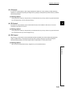
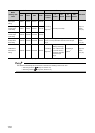
Buffer memory area name
Buffer memory address
Stored value Reference
CH1 CH2 CH3 CH4
CH Manipulated value (MV) Un\G13 Un\G14 Un\G15 Un\G16 -50 (-5.0%) Page 89, Section 3.4.2 (5)
CH Manipulated value (MV) for
output with another analog module
Un\G177 Un\G178 Un\G179 Un\G180 0 Page 133, Section 3.4.2 (47)
CH Manipulated value for heating
(MVh) (Un\G13 to Un\G16)
Un\G13 Un\G14 Un\G15 Un\G16 -50 (-5.0%) Page 89, Section 3.4.2 (5)
CH Manipulated value of heating
(MVh) for output with another
analog module
Un\G177 Un\G178 Un\G179 Un\G180 0 Page 133, Section 3.4.2 (47)
CH Manipulated value for cooling
(MVc)
Un\G704 Un\G705 Un\G706 Un\G707 -50 (-5.0%) Page 89, Section 3.4.2 (5)
CH Manipulated value of cooling
(MVc) for output with another
analog module
Un\G708 Un\G709 Un\G710 Un\G711 0 Page 133, Section 3.4.2 (47)