


12 - 3
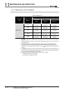
12.2 Troubleshooting Flowchart
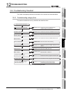
12.2.2 Flowchart for when the ERR terminal (negative logic) is off (opened)
12
TROUBLESHOOTING
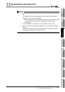
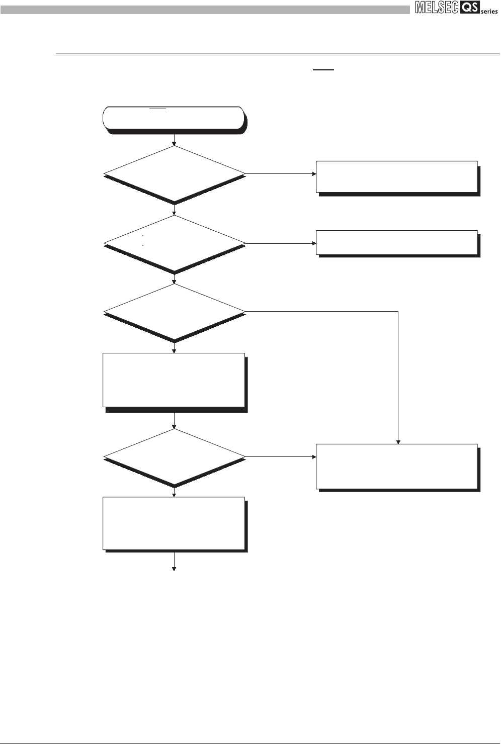
12.2.2 Flowchart for when the ERR terminal (negative logic) is off (opened)
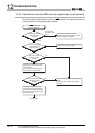
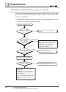
The following shows the flowchart for when the "ERR terminal" is off (opened) at power-on
or during operation of the programmable controller.
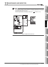
The ERR terminal has
turned off (opened).
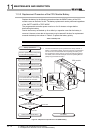
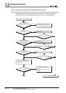
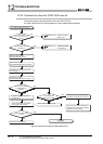
Remove the corresponding power
supply module, and mount it to the
normal base unit.
(Do not mount any modules other
than the power supply module.)
Mount the corresponding power
supply module to the original base
unit again, and remove all modules
other than the power supply module
from the base unit.
NO
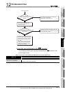
Flashing (CPU
module is in stop
error)
Conduct PLC diagnostics with GX
Developer to check error details and take
action according to the details.
On
The corresponding power supply module is
faulty
(Replace it with a normal power supply
module).
How is the "ERR."
LED of the CPU
module?
Not flashing
YES
How is the "ALIVE"
LED of the CPU
module?
Off
Supply power of proper voltage.
Is power supplied?
Is the power supply
voltage proper?
Off
On
How is the "POWER" LED
of the power supply
module?
(To next page)